Due Date on Course Website
ENGR 100 Assignment 1: Rocket Science
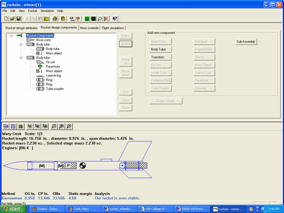
Figure 1. Example of RockSim design
Background
Questions
1. To find the best engine for your rocket, follow the steps below and fill in the table for each simulation you run.
|
Trial |
Engine Loaded |
Maximum Altitude |
Time to Apogee |
Altitude at deployment |
Optimal Delay |
Result? |
|
1 |
Example
B6-4 |
483.72 ft |
5.22 s |
479.57 ft |
4.47 s |
Okay – 4s delay is less than optimal but close enough |
|
2 |
|
|
|
|
|
|
|
3 |
|
|
|
|
|
|
|
4 |
|
|
|
|
|
|
In order to overcome these disturbances a rocket must have a stabilizing, restorative feature. Then, the disturbances will be damped out so that the rocket can go on its intended flight direction. A stable configuration has the Center of Pressure (CP), blue circle, located behind the Center of Gravity (CG), circle with black and white sections as shown in Figure 2.
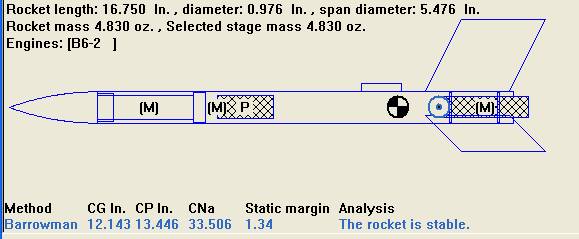
Figure 2. Rocket CG and CP Located
These two points represent balance points of the rocket. The Center of Gravity is the balance point for the mass of the rocket. For example, if you balanced your rocket length-wise on your finger, the point where it balances corresponds to the CG. The CG serves as the pivot point for all pitching (nose up or down) and yawing (nose left or right) and roll action during the flight.
The
Questions:
2. What will happen if the CG is behind the CP? Draw a picture w/ your answer.
3.
What is your static margin?
The distance between the CP and CG is known as the static margin.
The ideal distance between the two points should be approximately 2 times
the diameter of your rocket or a static margin of 2. For
example, if your rocket has a diameter of 1 in, the CG and CP should be
separated by 2 in.
Adding weight to the nose of the rocket will move the CG closer to the nose (use clay). Adding a larger (and thus heavier) rocket motor at the back of the rocket will move the CG towards the fins. A rocket will tend to be more stable when the CG is more towards the front of the rocket.
· To move the c.p., increase or decrease the size of the fins.
Larger fins cause the CP to move towards the rear of the rocket. A curved nose cone or the addition of small fins on the front of the rocket will move the CP forward.
5.
Did your rocket pass the swing test?
Perform a swing test to ensure your rocket is stable.
Tie a string around the rocket w/ engine at the CG and swing around your head.
If the rocket flys unstable or backwards do steps in #4 to fix rocket.