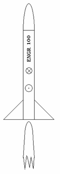
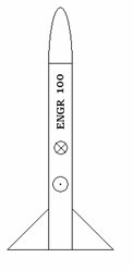
 |
 |
| Thrust phase | Coast Phase |
See Website for Due Date
ENGR
100 Rocket Design Assignment
Draw and label the force vectors to complete the free body diagram for a rocket in thrust phase and in coast phase.
 |
 |
| Thrust phase | Coast Phase |
Complete
Thrust ∑ F =
Coast ∑ F =
Define each term in the two equations. Through
which point (Center of Gravity or
Part Two
- Wind Tunnel Data
|
No.
Fins |
Fin
Size |
CD |
FD
(N) |
CP
Location (cm)* |
Static
Margin |
|
3 |
Tiny |
0.52 |
1.9 |
18.3 |
|
|
3 |
Small |
0.60 |
|
11.5 |
|
|
3 |
Medium |
0.65 |
|
9.6 |
|
|
3 |
Large |
0.70 |
|
7.8 |
|
|
4 |
Tiny |
0.62 |
|
12.3 |
|
|
4 |
Small |
0.64 |
|
9.8 |
|
|
4 |
Medium |
0.76 |
|
7.4 |
|
|
4 |
Large |
0.82 |
|
5.5 |
|
* The CP location is measured from the bottom of the rocket.
Complete the table by calculating the static margin and the drag force when the rocket is traveling at V = 100 m/s. The equation for drag force is FD = 0.5rCDAV2 where A is the cross-sectional area of the rocket tube (you may assume that the fins are very thin and do not contribute to the total cross-sectional area of the rocket).
Rocket parameters:
Diameter of rocket D = 2.8 cm
Center of Gravity is located 16 cm from the bottom of the rocket (the weight of
the fins is small so that the CG doesn’t change much with size and number of
fins).
Part Three –
Design Problem: