Road Design in St. Edward’s Park
By:
Adam Baines
Frederick Beck
Danielle Boudreaux
Daisuke Sakuma
Sara Wilson
Edwin Wong
Prof. Peter Schiess
Table of Contents
Executive
Summary
Objectives
The objectives of this project are to design a road for timber harvesting located in St. Edwards Park and to design a culvert crossing for two streams.
Site Description
The project site
is located in the northeast bank of
Design Approaches and Issues
Knowing that the management objective of this area is to produce timber, the design for this road will be centered in reducing the yarding distances during timber harvesting. The design vehicle for this road is a log truck with a 20 ft long tractor, a 10 ft stinger, and 30 ft from bunk to bunk. The Critical Vehicle is a lowboy with an 18 ft tractor and a 36 ft trailer. The grade of the favorable and adverse grades along the road makes the design speed 12 mi/hr or 20 km/hr.
Most of the side slopes were over 50 percent. This meant that a large portion of the road template had to be a full bench. This resulted in few balanced cut and fills.
Ditch drainage culverts were placed between 100 and 200 ft from the stream crossings and every 40 ft in elevation change. This resulted in the need for four 18 inch culverts.
Sedimentation
A total of four cross drains was established. The first cross drain satisfies both the elevation difference restrictions and stream proximity distance. Cross drains 2 and 3 are placed roughly 100ft from stream crossings. Cross drain 4 does not exceed 40 ft elevation change from road end while also being about 100ft from a stream crossing.
Average Annual Sediment Yield from the 4 cross drains was 13,301.56lbs, the 30 Year Mean Annual Averages from the entire road was 6,179.09 lbs and the Sediment leaving Buffer was 3,695.34 lbs.
Curve Widening Issues
and Approaches
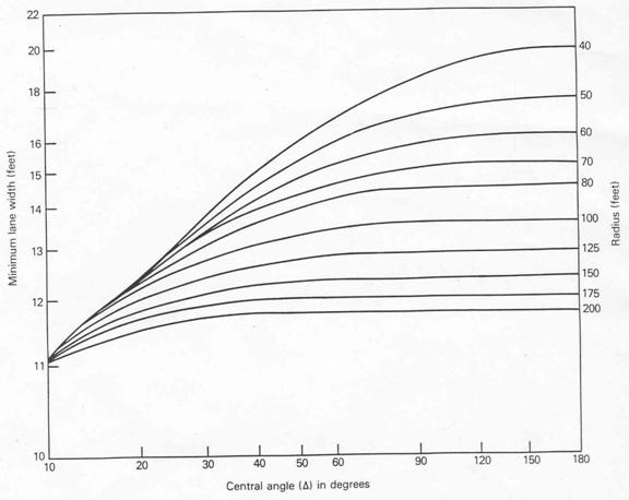
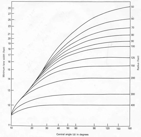
In this case, the vehicle with the largest off-tracking is the critical vehicle, a lowboy with an 18 ft tractor and a 36 ft trailer. For the first curve it was determined that the travel way had to be 25 ft wide and for the second curve a 29ft wide travel way was determined. The curve widening was applied to both sides of the centerline in order to not change road alignment.
Road Costing Estimate
The five main points for road costing were Clearing & Grubbing, Excavation & Hauling, Ballast and Surfacing, Culverts, and Move in & Move out of Equipment.
The total area to be cleared and grubbed is 2.18 acres for a total cost of $2,888.65. The total cost for excavation and hauling is $30,076.24. The total volume for Ballasting and Surfacing is 2658.91 yd3 for a total cost of $3,670.00.
There is 6 galvanized steel culverts along our road. Four will be placed intermittently along the length of the road and the other two will be placed at the stream crossings.
Move in and move out costs for a D6 Dozer ($450/ move, 2 moves), a front end loader ($250/move, 2 moves), a vibrating roller ($300/move, 2 moves), gravel trucks ($100/move, 4 moves), and a grader ($300/move, 2 moves) for total cost of $3,000.00.
Therefore, the total estimated cost for the construction of our designed road is $42,076.60 for no fish bearing streams, and $46,484.41 if the first stream is fish bearing.
Stream crossing culverts
A stream culvert of 21 inches will be placed in the first stream and for the second stream a 15 inches stream culvert will be used.
Both of these
streams are not fish streams because they both do not meet the requirements for
an F type (Fish bearing) stream. The first stream is either a Np (Non-fish
perennial) or a Ns, depending on whether it dries up during a year of normal
rainfall. The second stream is a Ns (Non-fish seasonal) because the stream bed
was already dry during the process of traversing.
Overview
of Design Approaches and Issues
In order to determine what the design vehicle and critical vehicles will be, the first thing that must be done is to establish the purpose of the road which is based on the management plan for the land. In the case of St. Edwards Park, the management plan is for recreation, so no road would be built. Therefore, for our purposes the management objective of this area is to produce timber. With this in mind we now know the road we designed is for reducing the yarding distances during harvest and the design and critical vehicles can be identified. The design vehicle for this road is a log truck with a 20 ft long tractor, a 10 ft stinger, and 30 ft from bunk to bunk. To get the logging equipment in, the Critical Vehicle is a lowboy with an 18 ft tractor and a 36 ft trailer.
The terrain of this site is steep, and in turn grades along the road are steep as well. These steep grades are the deciding factor in the design speed and not the number of curves because for the most part, the grades are greater than 6 to 8 percent (LIRA, 1980). The grade of the favorable and adverse grades along the road makes the design speed 12 mi/hr or 20 km/hr (See graph in Appendix A) (LIRA, 1980).
For designing the road, RoadENG was used and the steep terrain meant that the alignment of the road was based on vertical alignment because the side slopes were greater than 15 percent and this affects the procedure when designing the road. When the side slopes are less than 15 percent, Horizontal alignment is what determines the alignment of the road and the first window used in RoadENG would be the Plan view. Since the road alignment is based on vertical alignment, the first window used after the traverse data was entered was the profile view.
To vertically align the road, straight lines were drawn through similar grades along the traverse setting them to one grade. This reduced the number of changes in grade throughout the road; therefore, reducing the maintenance costs for the equipment using the road and the road itself because of the need for fewer gear changes. Next, the cross-sections were balanced horizontally so as to not change the vertical alignment. Most of the side slopes were over 50 percent. This meant that a large portion of the road template had to be a full bench. This resulted in few balanced cut and fills.
The road was then horizontally aligned in the plan view to minimize the curves in the road. Since the travel speed of the road is determined by grade and not numbers of curves, not much attention was paid to curve straightening. With adjusting the plan view, the cross-sections had to be re-balanced. This time the balance was done vertically so as to keep the horizontal alignment. The profile view was then checked to make sure that none of the sections of road went over 20 percent, because with any grade greater then 20 percent, an assist vehicle is required by Washington State Law.
Ditch drainage culverts were placed between 100 and 200 ft from the stream crossings and every 40 ft in elevation change. This resulted in the need for four 18 inch culverts.
Due to the large amounts of material created from the full benches, all areas that need additional fill or are through fills are within free haul distances of 300 to 400 ft from the necessary excess cut material. Since the road runs close to the stream, any wasting will need to be done away from the streams and deposition locations will need to be 300 to 400 ft road length away from the stream, starting from the end of the free haul material used for the fill in stream crossings. There will be no need for any borrowing because of the vast amounts of material being generated within free haul distance of the locations that need additional fill.
Table 1: Road description broken into similar segments.
|
Station |
Grade
(%) |
Travel
Way Width (ft) |
Road
Template |
Notes |
|
0+00 to 0+94.1 |
0 |
12 |
Through fill |
|
|
0+94.1 to 1+44.9 |
0 |
12 |
Balanced cut and fill |
|
|
1+44.9 to 1+70.4 |
0 |
12 |
Through fill |
|
|
1+70.4 to 2+50.2 |
-15 |
12 |
Through fill |
|
|
2+50.2 to 3+09.1 |
-16 |
12 |
Full bench |
|
|
3+09.1 to 3+28.5 |
0 |
12 |
Balanced cut and fill |
|
|
3+28.5 to 3+45.7 |
0 |
12 |
Full bench |
|
|
3+45.7 to 3+76.7 |
-15 |
12 |
Full bench |
|
|
3+76.7 to 3+88.2 |
-15 |
12 |
Balanced cut and fill |
|
|
3+88.2 to 4+18.9 |
-15 |
12 |
Through fill |
|
|
4+18.9 to 4+21.6 |
-15 |
12 |
Balanced cut and fill |
|
|
4+21.6 to 4+60.3 |
-12 |
12 |
Balanced cut and fill |
|
|
4+60.3 to 4+85.0 |
-12 |
12 |
Full bench |
|
|
4+85.0 to 5+30.8 |
-16 |
12 |
Full bench |
18 inch ditch drainage culvert at 5+30.8 |
|
5+30.8 to 5+68.8 |
-16 |
12 |
Balanced cut and fill |
|
|
5+68.8 to 6+26.1 |
-16 |
12 |
Full bench |
|
|
6+26.1 to 6+55.3 |
-16 |
12 |
Balanced cut and fill |
Taper from 6+26.1 to 6+55.3 for curve widening |
|
6+55.3 to 6+80.5 |
-16 |
25 |
Balanced cut and fill |
Beginning of first curve (PC) at 6+55.3, widening of 13 ft. |
|
6+80.5 to 6+94.5 |
-16 |
25 |
Through fill |
Fill needs to be engineered because over 20 ft tall. |
|
6+94.5 to 7+38.6 |
2 |
25 |
Through fill |
Stream culvert at 6+94.5. |
|
7+38.6 to 7+68.0 |
2 |
25 |
Full bench |
|
|
7+68.0 to 8+31.9 |
2 |
25 |
Full bench |
End of Curve (PT) at 8+03.3. Taper from 8+03.1 to 8+31.9 |
|
8+31.9 to 8+67.9 |
9 |
12 |
Balanced cut and fill |
|
|
8+67.9 to 9+16.3 |
9 |
22 |
Balanced cut and fill |
Turnout, 10 ft added to left of centerline. |
|
9+16.3 to 10+09.4 |
-4 |
12 |
Full bench |
|
|
10+09.4 to 10+77.6 |
-8 |
12 |
Full bench |
Taper from 10+32.7 to 10+77.6 for curve widening. 18 inch ditch
drainage culvert at 10+32.7 |
|
10+77.6 to 11+43.7 |
-8 |
29 |
Balanced cut and fill |
Beginning of second curve (PC) at 10+77.6. Curve widening of 17
ft. |
|
11+43.7 to 11+46.6 |
-8 |
29 |
Through fill |
Fill needs to be engineered because over 20 ft tall. Stream
culvert at 11+43.7. |
|
11+46.6 to 12+51.1 |
4 |
29 |
Through fill |
Fill needs to be engineered because over 20 ft tall. Taper from
12+01.5 to 12+51.1 |
|
12+51.1 to 12+78.7 |
4 |
12 |
Full bench |
18 inch ditch drainage culvert at 12+51.1 |
|
12+78.7 to 12+97.6 |
11 |
12 |
Full bench |
|
|
12+97.6 to 16+70.0 |
8 |
12 |
Full bench |
|
|
16+70.0 to 17+09.3 |
8 |
12 |
Balanced cut and fill |
|
|
17+09.3 |
|
12 |
Through fill |
End of Road |
Sedimentation
Road Drainage and
Cross Drain Spacing
Road Drainage is an important aspect of road design. Adequately allowing water to leave the road prism and controlling of the movement of water can extend the life of a road. Cross drain design and spacing is the road drainage solution. The spacing of cross drains was determined by at least one of these two reasons:
- a maximum of 40ft elevation difference between two cross drains limits the volume and speed accumulating in the ditch
- having a cross drains approximately 100ft from stream crossings allows for settling of sediments prior to the drainage entering a stream.
By following these criterions, the result is a total of four cross drains. The first cross drain satisfies both the elevation difference restrictions and stream proximity distance. Cross drains 2 and 3 are placed roughly 100ft from stream crossings. Cross drain 4 does not exceed 40 ft elevation change from road end while also being about 100ft from a stream crossing.
WEPP Models
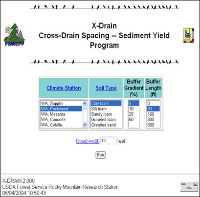
The Forest Service WEPP Interfaces (FSWEPP) can aid in the determination of cross drain spacing by determining sedimentation amounts and assess sediment amounts from existing roads. WEPP: Road and Cross Drain (from FSWEPP) are internet based programs to model forest road erosion and sedimentation based on simple parameters (input screens Appendix B). The results from the two programs are as follows:
Cross Drain (X-Drain)
Average Annual Sediment Yield from 4 Cross Drains (Appendix C.)
13301.56
lbs
Cross Drain (X-Drain) based on five input parameters gives you an output table to determine sediment yield from road gradients and cross drain spacing combinations. The model seems very simplified with limited input parameters such as buffer distance is limited to 0, 33, 160, 330, & 660. For the first segment of the road with the first cross drain, if one changes the buffer distance selection between 33 or 160 and looks at an 8% 400ft road segment the average annual sediment yields differ by ~5000 lbs (Appendix C).
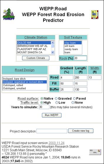
WEPP: Road
30 Year Mean Annual Averages from entire road (from segments) (Appendix D.)
Road Prism Erosion - 6179.09 lbs
Sediment
Leaving Buffer - 3695.34 lbs
WEPP: Road utilizes more input parameters not restricting to a selected number sets and the output is specific to the data entered. WEPP: Road allows the user to specify traffic level and road surface which affect the sediment yields and should be accounted for.
Curve
Widening Issues and Approaches
When curves are incorporated into the design of the road, the design must account for off-tracking and the road width must be increased to allow for this off tracking. The amount of curve widening that is needed is determined by the vehicle that must use the road that has the largest off tracking. In this case, the vehicle with the largest off-tracking is the critical vehicle, a lowboy with an 18 ft tractor and a 36 ft trailer. On our road the lowboy will have to navigate through curves that are also stream crossings. The first curve had a 60 ft radius and a central angle of 144 degrees. Using a chart in Cain and Langdon, 1982 (Appendix F), it was determined that the travel way had to be 25 ft wide. The second curve had a 50 ft radius and a central angle of 143 degrees. Using the chart in Cain and Langdon (Appendix F), it was determined that the travel way had to be 29 ft wide. The curve widening was applied to both sides of the centerline in order to not change road alignment.
Road Costing
Estimate
The five main points for road costing are:
- Clearing & Grubbing
- Excavation & Hauling
- Ballast and Surfacing
- Culverts
- Move In & Move Out of Equipment
The total area that needs to be cleared and grubbed is 2.18 acres; and at a cost of $1325/acre for the “light” vegetation class of our terrain (Light brush, few cull logs, etc), the total cost of clearing and grubbing for our road is $2,888.65.
The total base cost for excavation and hauling is $1/yd3. An additional $.70/yd3 is needed for controlled compaction since most of our road has steep side slopes. Our stream crossings require an additional $.86/ft(linear) for benching, which is needed due to the large fill areas. The costs for the above labor breaks down to $139.37 for the Grader, $66.00 for the Operator, $36.96 for the Laborer, and $44.88 for a 4x4 truck, with a total cost of $287.21. With a total cubic excavation yardage of 17365.9 yd3, 300 linear feet of curve length, and a labor cost of $287.21, the total cost of excavation and hauling is $30,076.24.
Ballast and Surfacing consists of digging and loading the ballast, hauling and spreading, compaction, stripping the ground, and reclamation. The sum cost of these parts is $1.38/cubic yard, and with a total cubic yardage of 2658.9111 yd3, the total cost of ballast and surfacing for our road is $3,670.00.
There will be 6
galvanized steel culverts along our road.
Four will be placed intermittently along the length of the road and have
a diameter of 18 inches (cost/ft:
$10.30) with two of those measuring 24.2 feet long and the other two
26.1 feet long. The other two will be
placed at the stream crossings, with the first having a 21 inch diameter
(cost/ft: $12.15) and a length of 72.2 feet, and the second having a diameter
of 15 inches (cost/ft: $8.48) and a length of 62.3 feet. The total cost for all culverts on our road
will thus be $2,441.71. These costs
are based on neither of the streams being classified as fish bearing. If the first stream were found to contain
fish, two 60 inch diameter pipes (cost/ft: $36.60) with a length of 72.2 feet
would be used instead of the 21 inch diameter culvert above. In this case, the total cost for all culverts
would be $6849.524.
Move in and move out costs for a D6 Dozer ($450/ move, 2 moves), a front end loader ($250/move, 2 moves), a vibrating roller ($300/move, 2 moves), gravel trucks ($100/move, 4 moves), and a grader ($300/move, 2 moves) total $3000.00.
Therefore, the total estimated cost for the construction of our designed road is $42,076.60 for no fish bearing streams, and $46,484.41 if the first stream is fish bearing. (Appendix E)
Stream
Crossing Culverts
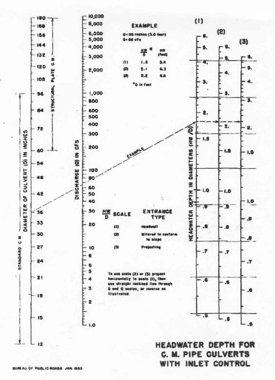
Stream culverts must be large enough to handle a 100 year rain event (Hydraulics Manual). To determine the size the stream culverts, we need to determine the stream discharge (Q) and drainage area for the stream crossings. To see process for determining these parameters see Appendix G. The first stream crossing has a drainage area of 49 acres and a Q100 of 6.29 cfs. The second stream crossing has a drainage area of 17 acres and a Q100 of 2.53 cfs. Next, the Inlet Control Nomograph (Appendix G) was used to determine the size of the culvert needed using a headwater depth to culvert diameter of 1 to get a stream culvert of 21 inches and the culvert for the second stream is 15 inches in diameter (Hydraulics Manual).
Both of these streams are not fish streams because they both do not meet the requirements for an F type (Fish bearing) stream. For a stream to be an F type, the basin size must be greater than 50 acres for the west side of the Cascades and the defined channel within the bank full width less than 2 ft (Grizzle). The first stream is either a Np (Non-fish perennial) or a Ns, depending on whether it dries up during a year of normal rainfall. The second stream is a Ns (Non-fish seasonal) because the stream bed was already dry during the process of traversing. If the stream was large enough to be considered an F type stream or was surveyed and found to have fish within it at least part of the year, then the culvert would have to allow for the passage of these fish. According to the Design of Road Culverts for Fish Passage on the Washington State Fish and Wildlife website, the size of the culvert can be determined by the
No-Slope, Hydraulic, and the Stream-Simulation design options. The No-slope and Hydraulic design options are used for streams with bed gradients that are small. For our stream, the gradient of the streambed is 10 percent; therefore, these two techniques result in water velocities that are very high and would be a barrier to fish passage. The Stream-Simulation design option would be used to decide on the culvert size (See Appendix G for equation used). The result is a culvert that is 9.2 ft in diameter or greater for a 6 ft bank full width. The culvert type that could be use would be either a half culvert with footings, or a regular culvert half buried in the stream bed.
According to Design of Road Culverts for Fish Passage, both types of culverts would be similar in cost. Multiple culverts can be used to reach the desired size of the culvert like two 5 ft diameter culverts. In fact, having multiple culverts can be preferred for less convergence of the up stream flow and the amount of fill and ballast can be less. (Stone R.P, 1992)
Appendix A
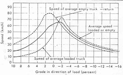
Figure 1: Travel speed of loaded and empty logging truck on adverse and favorable grades.