ENGR 100
Bridge Component Tests
Purpose
The
purpose of this activity is to simulate the “Research and Development”
aspect of engineering. Your team
will act as “engineering researchers” completing a series of component tests
to determine the strength and characteristics of the bridge materials.
In the end, you will compose an individual memo addressed to the design
team summarizing your findings and recommendations.
Once this is completed, you will then switch roles, becoming the
“designer”, and use this information directly to design and build your
team’s prototype bridge.
Group Assignment
The
class will work together on this assignment, with groups completing different
tests and then sharing the results. The
following is a list of tests:
Test 1 - Tension
Test
Test 2 - Compression Test
Test
3 – Torsion and Bending Test
Test 4 - Fishline Tension Test (Optional)
At
the end of class, each team will write their results (tables, graphs, findings)
on the board for everyone to copy. Each
team will then present and explain their findings and we will have a short
discussion about how these findings will be useful for bridge design.
Individual Assignment
Each
person will be responsible for writing a memo summarizing the results of the
tests and making recommendations to a fictitious design team.
The purpose of writing this memo, even though you are essentially the
design team for whom it is written, is to be introduced to the fundamentals of
technical writing.
Feel free to experiment! If you have any ideas about how to
change a test or perform additional tests, please let the instructor/TA know.
Test 1 - Tension Test
Objective
The
objective of the tension test is to determine a recommended overlap distance for
two tongue depressors in tension (taking into account strength and total span
length).
Procedure
- Build the test specimens by gluing two tongue depressors together using
different lengths of overlap ( max. < 3/4"). Be
sure to test at least 3 specimens for a given overlap distance to ensure more
accurate results. Reinforce the hole with extra pieces of tongue
depressor.
- Place the sticks in the vice on the testing platform and reinforce the hole at
the other end with tape. Test the
sticks by pulling straight up with the force gauge.
Record the forces (in lbs) required to break each of the specimens in
your notebook. Also note how each
specimen failed!
- If you are getting inconsistent results, create several more specimens and try
to standardize your testing methods.
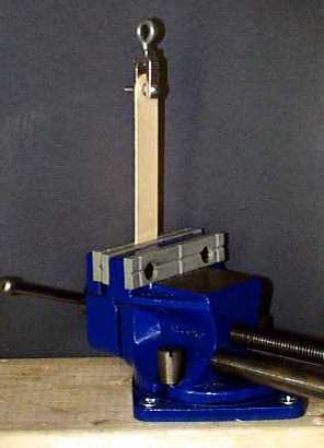
Figure 1. Tension Test
Deliverables
(to be included in the memo)
- How
did the different specimens fail?
- Why
you think they may have failed at different places?
- What
is the relationship between failure force and overlap length?
From examining the results, what would you recommend for an overlap length?
Why?
If
you have more time…
Do
a similar test using elmers or wood glue.
How do the results compare?
Test 2 - Compression Test
Objective
The
objective for Test 2 is to determine a maximum length that designers should not
exceed, to ensure adequate strength from compressions members.
Procedure
- Use a ruler to prepare several
specimens for the compression test ranging in length from 3” to about 10”.
For members greater than 6”, glue two tongue depressors together with
a 1” overlap length and then cut the ends to the desired length.
Prepare at least 2 samples for each length to ensure some level of
accuracy.
- To
test the specimens, place them upright on the scale and push down as shown
in Figure 2 (using pliers may be easier on your hands).
Record the force (in grams) required to bend the specimen.
Convert the grams to lbs in EXCEL.
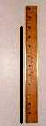
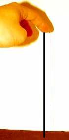

Figure 2. Compression Test
Deliverables
(to be included in the memo)
-
Does the location of the 1" overlap glue joint (end
or middle) affect the buckling strength?
-
Create a table
in Excel showing the specimen length in one column and the failure force
in another (conversion for g to lbs: Force (lbs) = (Scale Reading/1000)*9.81*0.2248)
-
Plot the Force
(lb) vs. Length (in) (For accuracy, use "x-y scatter"
graph not a line graph).
-
Look at the graph to see how the force changes as the
length changes. Is there a
particular point on the graph where the force required to buckle the specimen
decreases signficantly with little change in length?
If so, the bridge design team should be notified of this length so
they can avoid designing a bridge with compression members that are prone
to buckle under smaller loads.
Test 3 –
Torsion and Bending Test
Objectives
The
objective for Test 3 is to determine effective bracing methods to maximize
strength of a platform in bending and torsion.
Procedure
- Brainstorm different bracing methods
for a platform 11 inches long and 2 ½ to 4 inches wide.
Show sketches to the instructor or TA before you build them. See link
for examples.
- Construct several platforms using
a maximum of 16 sticks each. Each platform should have a distinct bracing method that can
be described and compared to other platforms.
Ask the TA/instructor to cut pieces using the band saw.
- Perform a
bending test on the platform by bending the ends up into a shape of a
“U”. Note the relative flexibility and strength.
- Perform a
torsion test on the platform by twisting the ends and noting the relative
flexibility and strength.
Deliverables
(to be included in the memo)
- What different
bracing methods were used?
Which were the strongest?
- Did the orientation of the tongue
depressors (flat or standing on the edge) affect the performance?
- Did the way the platforms were
constructed or number of sticks used affect the results?
If yes, how?
- What recommendations would you
give to the bridge design team for bracing?
Test 4 – Fishline Tension Test
Objectives
The objective for Test 4 is to evaluate different brands of fishline, measure their force - strain relationship and determine which brand has the highest stiffness.
Procedure
- Attach one clamp to the back of your work table.
- Obtain samples of the three (or more) brands of fishline. Approximately 45-50 inches of each.
- Tie no slip loops in the ends of the fishline.
- Measure the distance between the knots (L0).
- Apply tension loads in increments of two lbs using the force gauge and record the "stretch" length.
- Plot force versus strain for each brand of fishline using Excel. Strain is given by (L - L0) / L , where L is the "stretch" length.
Deliverables (to be included in the memo)
- What materials are the different brands of fishline? (You might need to do a little online research).
- Did the fishlines consistently break at a certain location? If so, where?
- Plot Force (lb) versus strain in Excel for the three (or more) samples of fishline.
- What recommendations would you give to the bridge design team for fishline use?
Click here
for data sheet.