CULVERT DESIGN Intro/Background This crossing is being installed because it is necessary to cross Miner Creek, in order to access the timber that is in behind it. The crossing is to be installed approximately 15 stations up Miner Creek, which is a feeder to the Little Washougal. At the time of this design, no information was available about the cross section of this crossing. Because of this, assumptions had to be made which resulted in the design being based on minimum requirements. It is important to note that these specifications and recommendations should be used as a guide, and if found to be in any violation of Washington State laws, should not be incorporated into the final design. Due to the fact that there are questions as to whether or not the creek could support fish, the decision was made that the final design must allow for fish passage. To expand on this point, the final design for crossings, regarding fish passage, will be in total accordance with the Washington Administrative Code, which outlines the requirements. Ken Bates, at the Department of Fish and Wildlife in Olympia, referred this document to us:
In order to ensure that there is an applicable design whether there are fish present or not, we have included a design which has the minimum requirements for fish passage, and one that does not. We have found using the USGS method that at the point of the crossing, the 100-year discharge is approximately 64.3 cfs. It should also be mentioned that the crossing occurs in the middle of a switch back so that there was limitations on the minimum width for both the road and the crossing.
Culvert Design Process Used in Design of Culvert The following, is the process and methods used in determining an adequate design. This process should be followed each time a culvert design is undertaken, in order to account for all of the key parameters.
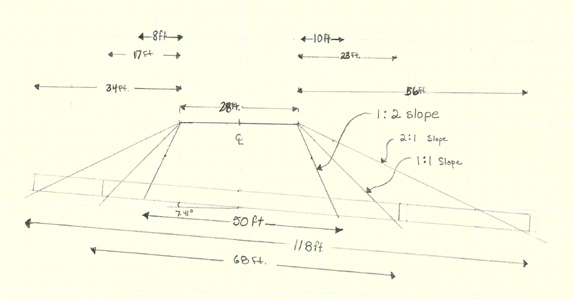
Establish Givens/Assumptions Side slope ratios Slope ratios for the culvert design have a direct impact on the length of the culvert. For this reason, we used three different slope lengths in order to aid us in deciding which would offer the most advantageous results (see diagram above). There are no set slope ratios, but the reference, Route Location and Design suggests a 2:1 ratio. The three slope ratios we assumed were 2:1, 1:1, and 1:2. The steeper the slope the shorter the culvert. The limiting factor here is that as the slope increases, cost increases in order to minimize erosion. Although the 2:1 will erode the least with minimal armament, the length of culvert is considerably longer. On the other hand, if a 1:2 ratio is used, the culvert is much shorter, but the cost to armor the slopes increases due to the need of retaining walls or rock gabions. 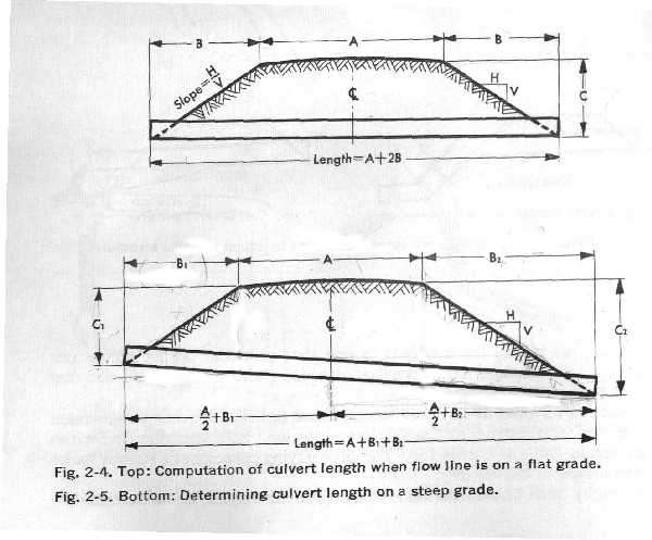 Figure 2-4, Handbook of Steel Drainage and Highway Construction Products (page 82). Assumed road width The width of the road was assumed to be 14 feet plus 14 more feet of curve widening (based on the curve widening equation in the Forest Service Handbook on page 4.24-9), in order to accommodate our design vehicle, a HS 25-44, which was used for the bridge design. As stated in the introduction, the point of the crossing occurs at a switchback so that a 60-ft. radius was used in coming up with these specifications. The width of the road will also act as a limitation on the length of the culvert, but cannot be varied.
Assumed height of fill above culvert This figure was taken directly from the 1998 Senior Class Management Plan for the Washougal Landscape on page 74. Due to the fact that we have not been on sight to verify this value, the value of 20 feet from the flow line to the surface of the road will have to be verified prior to building. Calculations Stream gradient The stream gradient was estimated from the Washougal Project Area Final Map-Proposed Roads and Unit Layout. The rise and run were measured in the section of Miner creek where the culvert will be placed. The rise and run were then divided to calculate a percent slope of 13%. Length of culvert The length of the culvert was determined using a graphical method. It was done this way due to the steep gradient which did not allow us to use the standard equation described in the Handbook of Steel Drainage & Highway Construction Products, which does not take into consideration gradients over 5%. We believe that our calculations still retained the necessary accuracy for the project. Discharge values The discharge values were calculated using the USGS method. As stated in the WAC, the Q (discharge) values must be computed for the 100-year event for maximum passage, and the 2-year event for the minimum flow and fish passage needs. Diameter of culvert The diameter of the culvert was calculated by using the Design of Small Dams Manual (pg. 561). Because we knew the average Q value, we were able to manipulate the graph/table in way that allowed for the 100-year event to not exceed the maximum capacity of the pipe. Through trial and error, we decided on a 60-inch pipe, which would pass the 100-year event at 80% full and the 10-year event at 50%. This is due to the fact that the WAC stipulates that a culvert must be buried approximately 20% of its total diameter. In this case, the culvert must then be buried approximately 12 inches. Then we made a gross assumption that the culvert would then act as 48-inch culvert in terms of capacity, etc. Depth of water in pipe The depth of the flow in the pipe was calculated using the Design of Small Dams Manual (pg. 561) much the same way the diameter was calculated. If discharge and diameter are known, the flow in the pipe can be calculated by simply extrapolating out a line to the flow column of the table. Velocity of water in pipe The velocity of the water in the culvert was calculated using Manning's Equation, Q=(1.49/n)*A*R2/3*S1/2. Since Q = V*A, this equation was substituted into Manning's Equation. So, the velocity was calculated using the following modified equation: V*A=(1.49/n)*A*R2/3*S1/2. Hydraulic Drop Since the culvert will be layed in at the same grade as the stream bed, there will be no hydraulic drop.
Environmental Considerations
Erosion control
Energy dissipation required The WAC stipulates that the flow from the culvert can not create erosion down stream. Due to the fact that the largest discharge from the pipe will be approximately 64.3 cfs, adequate dissipation can be obtained by strategically placing 24 inch rip wrap in the stream in a way that breaks up flow, but at the same time does not minimize constriction. Slope armament The base of the fill slope should also have a rip rap armament in order to minimize erosion up to the point of the 100-year event at both ends of the culvert, as stated in the WAC. The size of this material could vary according to available materials but we recommend that it be no less than 12 inches. It should also be noted that the WAC stipulates that the slopes must be revegetated with in one year of completion, with an approved native woody species, in order to minimize erosion.
Fish passage Species Although there are many possible fish species that might use Miner Creek, the design fish is the trout that is < 6 inches. Fish characteristics The culvert is designed for a trout that is < 6 inches. This is because this fish is the limiting factor; all of the other species can handle greater velocities and have similar needs in terms of depth. This criterion was verified with Ken Bates of the Washington State Fish and Wildlife Department. Maximum allowable flow velocities and depth requirements
Table from WAC 220-110-070
It is clear that the maximum allowable velocity for the flow in the culvert cannot be greater than 4 ft per second, for culverts between 1 and 200 feet in length. This specific aspect will not allow this design to pass fish because the culvert velocity is 13.8 ft per second.
Specifications
 Proposed Culvert Design
(If more than one alternative, the recommended specifications are in Bold Text) Recommendations and Concerns At this point, we do not know if the culvert will require fish passage. This will have to be determined prior to installation. Because of this we feel that the above design is the best possible alternative for a culvert installation, although it will not pass fish. It should be noted that the WAC does not allow baffles, weirs, or any other flow dissipaters to be installed in new culverts. These applications can only be used in retrofitting existing culverts. We know that the culvert design will not pass fish because the maximum allowable value for average allowable velocity in the pipe is 4.0 ft/sec for fish passage, and our culvert velocity is 13.8 ft/sec. This is due to the fact that flow velocities in the pipe are much higher than the design fish can handle in regards to fish passage. If fish passage is necessary, then a design that allows for adequate velocities and an undisturbed streambed will have to be used (see Pipe Arch Design).
Pipe Arch Design A pipe arch design is being provided so that if fish passage is necessary, a design will be available. The value added by the pipe arch is that it will allow passage over the stream, but at the same time, the streambed will remain in its natural state. Indirectly, this means that fish may still pass, due to there being plenty of cover and lower velocities created by the natural environment of the stream (i.e. large boulders creating eddy's etc.). Process Used in Pipe Arch Design It should be noted that the same process as the culvert design will be used, so only parameters that will change due to a pipe arch being installed rather than a culvert will be mentioned. Otherwise, simply refer back to the culvert design for specifications and reasoning. Establish givens/assumptions Side slope ratios The same slope ratios can be used as in the culvert design. Width of road The same road width must be used as in the culvert design. Height of fill above pipe arch The height of fill above the pipe arch is 20 ft. minus 3.33 ft, which gives us a fill above pipe arch of 16.66. The reasoning follows the culvert design for calculating fill above culvert. Installation Requirements for pipe arch As stipulated in the WAC, the footings of the pipe arch must be buried sufficiently deep so as not to become exposed by scour within the pipe arch.
Calculations
Q values The same values and reasoning as the culvert design. Span and Height of pipe arch In determining the height and span of the pipe arch, we used the Forestry Practices Field Guide of Oregon 1998 (Pg. 5-4), because the Washington State Forest Practices did not mention pipe arches. The calculation was based on knowing a flow capacity in cfs, and then equating it to a specific span and height. For our case we went with a known cfs of 70, so the result was a 65" by 40" pipe arch. Length of pipe arch The same values and reasoning as the culvert design. Environmental considerations
Erosion There should be minimal erosion caused by installing a pipe arch because the streambed should be unaffected. It will still be necessary to armor the slopes to the 100-year flood level as outlined in the culvert design for armament. Fish Passage If there are fish utilizing the stream, they should have adequate passage due to the streambed remaining in its natural state.
Specifications of Pipe Arch Design
 Proposed Pipe Arch Design
Recommendations and Concerns It seems clear that if fish passage is needed, the pipe arch design is the definite choice. This is because it not only allows for an adequate crossing, but also does not impact the streambed in any way, as long as necessary erosion measures are taken. The consideration with the pipe arch is the cost when compared with the culvert. A cost analysis should be conducted in order to understand this relationship. |