|
Week 1: Die Attach
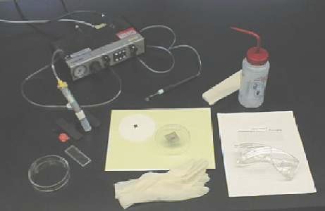
Equipment used for the die attach procedure.
top
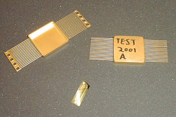
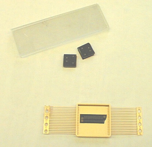
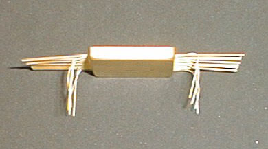
Dual Inline Hybrid Package and Die. (Package Labeling also shown.)
top
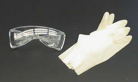
Eye protection and gloves. (We are using adhesive
under pressure and would like to prevent skin sensitizing to the epoxy.)
top
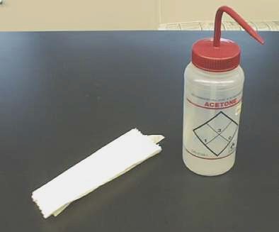
Acetone and tissues (swabs not shown).
top
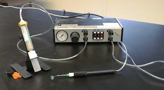
EFD 1500DV air powered adhesive dispenser with vacuum pickup pen.
top
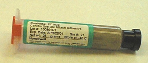
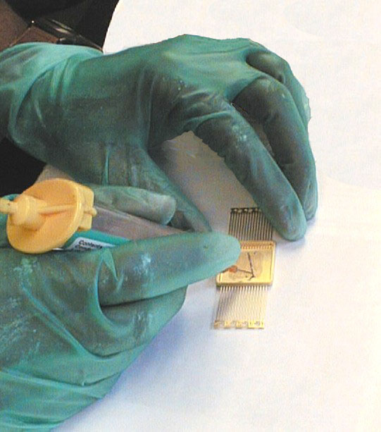
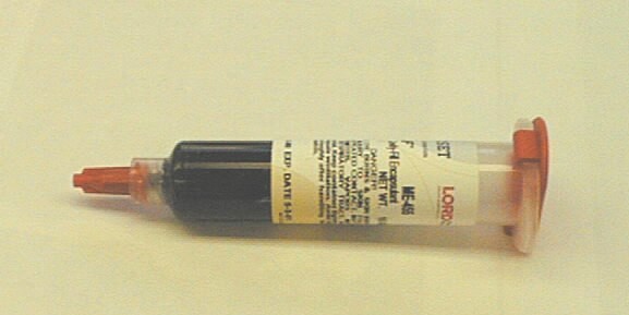
Die attach adhesive cartridge (Honeywell EC1030).
top
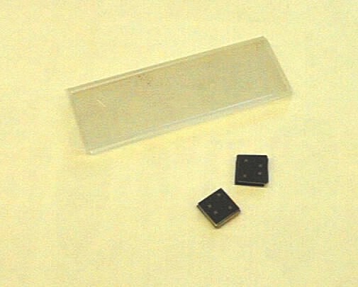
Glass slides and spacers for application of bonding pressure.
top
Clean die and package bond surfaces prior to bonding with acetone and
swabs/tissues.
top
Practice dispensing the die attach "X".
top
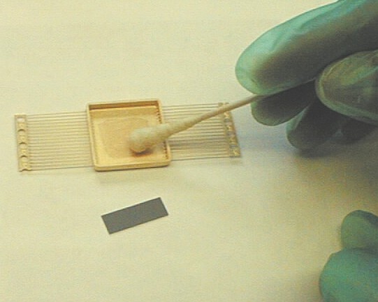
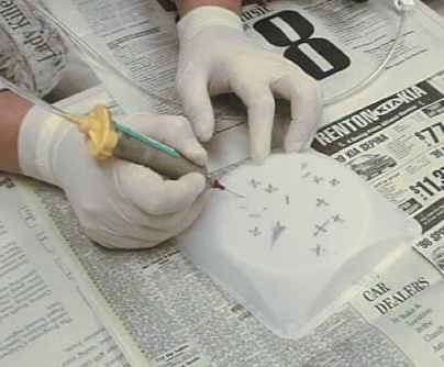
Dispense adhesive "X" on package surface.
top
Pick up die using the vacuum pickup pen.
top
Place die in package on the adhesive "X" using the pen.
(Carefully align top edge of die with the proper leads.)
top
Die positioned correctly on top of adhesive X with spacers and slides ready.
top
Apply gentle pressure to die by placing one of the provided spacers on the
die using the pickup pen and then carefully placing ~6 glass slides on top.
top

Students' package assemblies ready for curing.
top
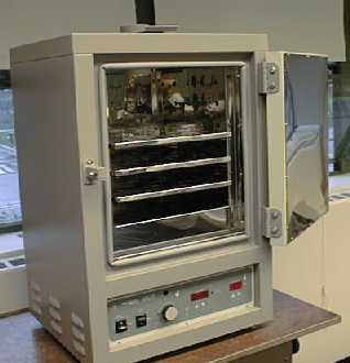
Cure in oven at 150°C for 1 hour.
top
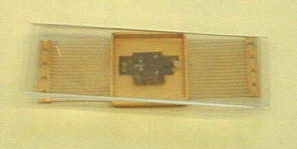
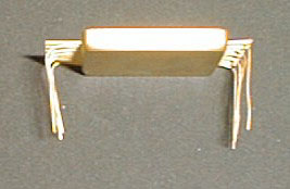
Package with cured adhesive. (Leads clipped for resistance measurement.)
top
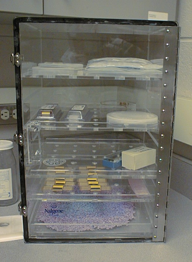
All of the student packages are then placed in the dessicator to await wire
bonding in week 2.
top
Week 2-3:
Wire Bonding and Encapsulation
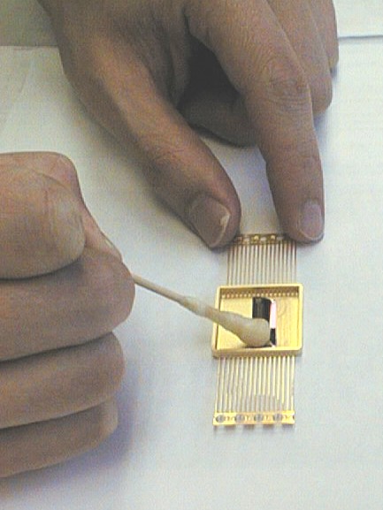
Clean die surface with acetone prior to wire bonding.
top
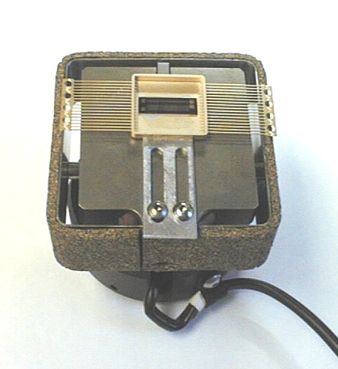
Attach package to the pre-heated work holder for the Westbond 7700C wire
bonder.
top
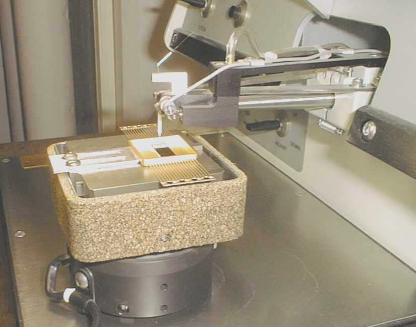
Thermosonic wire bond from the pads on the die to the leads on the package as
designated in the lab handout. (Note: Ball bonds are on the die
and wedge bonds are on the leads.)
top
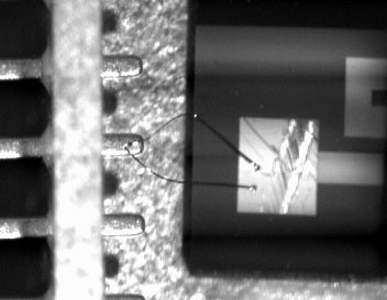
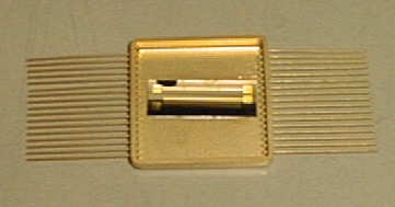
Die mounted in Dual Inline Hybrid Package with completed wire bonds.
top
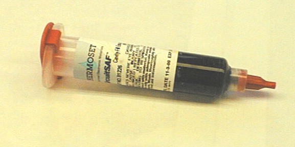
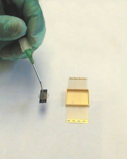
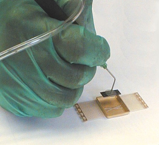
Encapsulant cartridge (Thermoset ME-455).
top
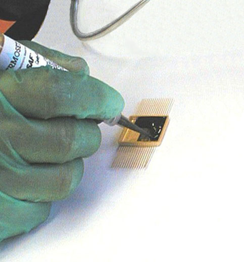
Fill Cavity with the ME-455 Encapsulant. (Note:
The end connector on the leads has been removed prior to this point.
This was necessary to allow measurement of the resistances through the
leads.)
top
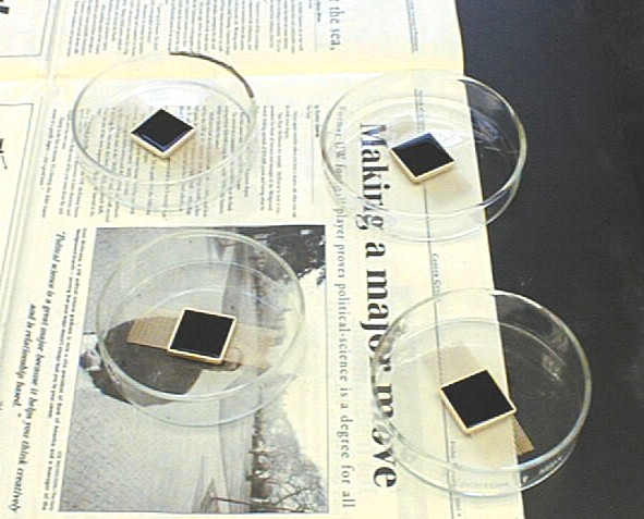
Student Packages in glass petri dishes ready to be cured. (Dishes allow
safe handling of packages with uncured encapsulant and will contain spills.)
top
Cure in oven at 150°C for 30 minutes.
top
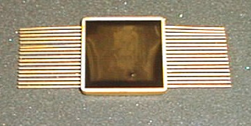
Our completed first level package.
top
Week 3:
Soldering to PCB

Tools required for soldering first level package to PCB.
top
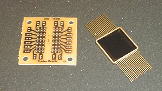
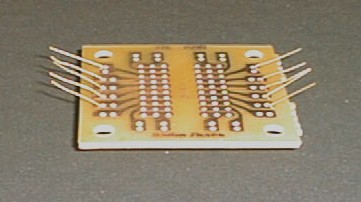
First level package and PCB.
top
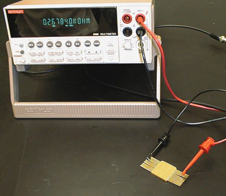
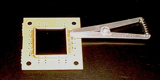
Measure resistance to verify intact wire bonds.
top
Bend numbered
leads on the package to insert through holes in PCB.
top
Clip remaining leads.
top
Package on PCB with leads bent outward. (Note: proper position of leads
in the proper holes as noted in the lab manual.)
top
Heatsink clipped to a lead before soldering. (The heat sink will
protect the die and the package from being damaged by heat during soldering.)
NOTE: The heat sink must be attached to the lead
being soldered and then moved each time.
top
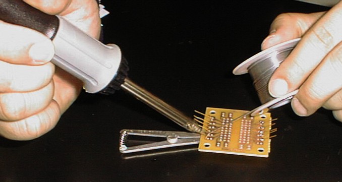
Solder the leads individually. Remember that
proper soldering technique requires that the tip of the soldering iron touch
both the lead and the pad on thc PCB. The solder is then applied to the
joint AFTER it is hot. This will insure a good solder bond to
both the lead and the pad. (A good bond can be checked by insuring that
the solder has "wetted" both the lead and the pad.)
top
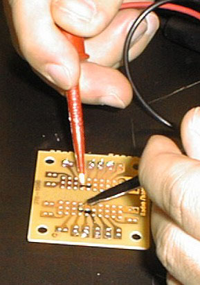
After clipping the soldered leads, the resistance is measured between the
copper pads on the PCB (this measures the entire circuit including soldering,
wire bonds and the traces on the die). This is
the resistance we will track during further testing.
top
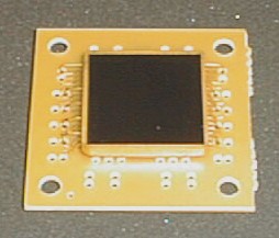
Our completed 2nd Level Package is now ready for environmental testing in Lab
3.
|