
Introduction to Geographic Information
Systems in Forest Resources |
Exercise: Model Building
Objective:
- to learn the use of the ArcGIS model builder for streamlining work flows
- Perform drive
substitution to create drives L (CD) and M (removable drive).
- Make a directory for today's exercise
- Model Building
Perform drive substitution
Perform drive
substitution to create the virtual drives L and M.
Make a directory for today's exercise
- Make a directory called M:\model_building to store today's data.
- You may want to delete other data from your removable drive to free up space.
I suggest keeping copies of all your old assignments somewhere (you can use
your dante account for this), but if you continue to store data on your removable
drive, you will eventually run out of space somewhere during the quarter.
If you still have the shapefile of the culvert inventory zones from the data
entry lesson, it will be used in today's lesson, so do not delete that, but
if you have already deleted your copy, you can download a copy during that
part of today's lesson.
Model Building
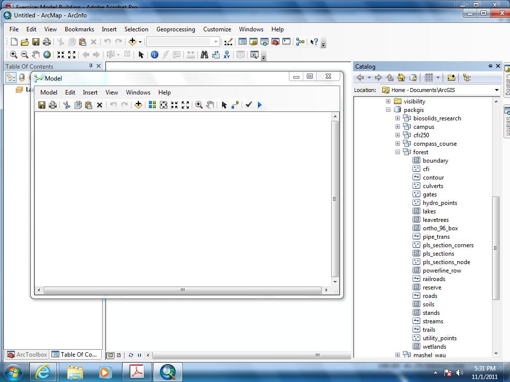
In ArcMap Version 10, you only need to click on the "ModelBuilder Window" icon  from the menu bar, and you can open the model builder. In this exercise, you will create a model that summarizes the area of different
soil names and forest age classes within a constant width road buffer.
from the menu bar, and you can open the model builder. In this exercise, you will create a model that summarizes the area of different
soil names and forest age classes within a constant width road buffer.
- Click the "Model Builder Window" icon from the menu bar.
- The new model will open.
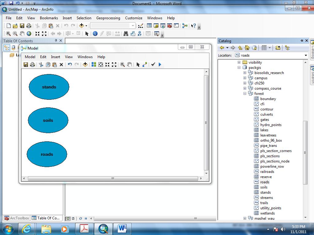
- Click the ArcCatalog window from side menu, navigate to L:\packgis\packgis.mdb\forest, and import the 3 layers, roads, soils, and stands into the ArcMap TOC (Table of Content) window first, then drag those three layer into the Model Builder Window.
- From ArcToolbox, find and drag into the model each of the Analysis Tools:
Overlay
> Intersect,
Overlay > Clip,
and Proximity > Buffer
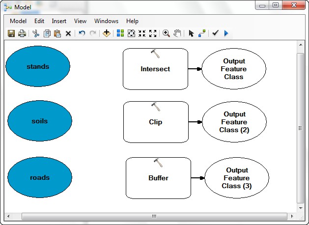
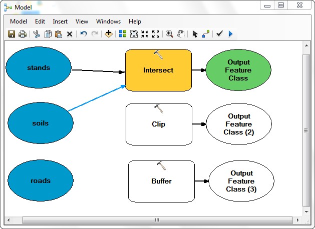
- Use the Connect tool
 to connect the stands and soils to the Intersect
tool. (Select "Input Features" for both layers)
to connect the stands and soils to the Intersect
tool. (Select "Input Features" for both layers)
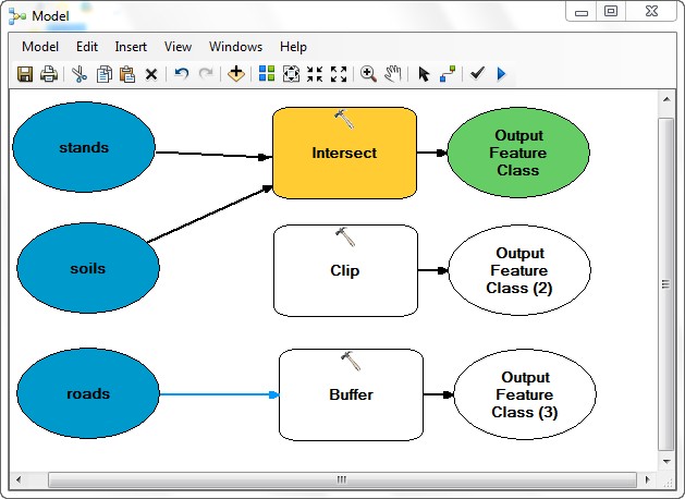
- Use the Connect tool again to connect roads to the Buffer
tool (Select "Input Features").
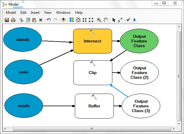
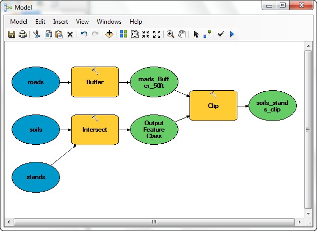
- Connect the Output of Intersect (Output Feature Class) as the input feature and the Output of Buffer
(Output Feature Class (3)) as the clip feature to the Clip tool.
- Switch Connect to Select operation, then double-click the Buffer tool to sets its parameters.
- Set the Distance to 50 Feet.
- Set the Output Feature Class to road_Buffer_50ft
in your geodatabase.
- Scroll down and set the Dissolve Type to All.
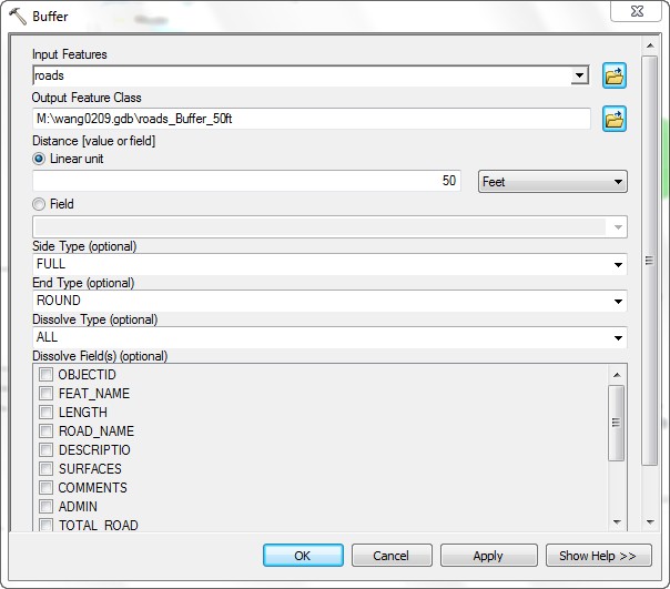
-
This parameterizes the buffer tool so that it will use these settings
during run time.
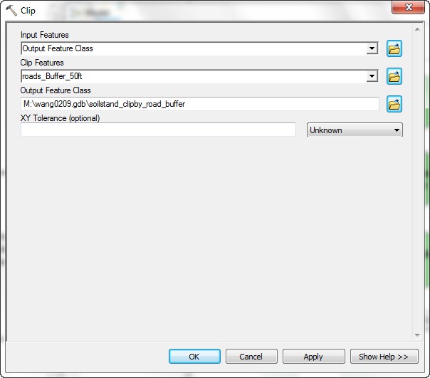
- Open the Clip tool to check the setting is done.
- The Input Features is the Output of the Intersection (Output to Feature Class).
- The Clip Features are the Output of the road buffers (roads_Buffer_50ft).
- Set the Output Feature Class to soilstand_clipby_road_buffer.
- The Intersect tool does not need to be parameterized because
there is no order of precedence for intersection.
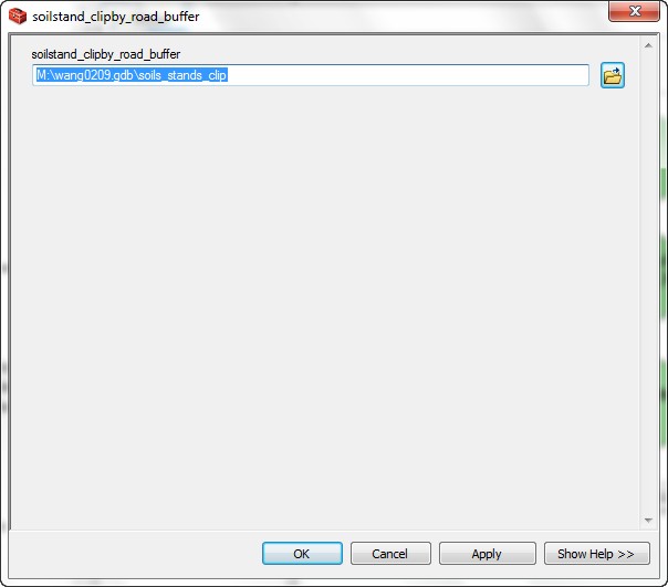
- Right-click and rename the final data set at the right hand side of the model to soils_stands_clip.
- Click the Auto Layout button
 and the Full Extent button
  to get a better view of the model.
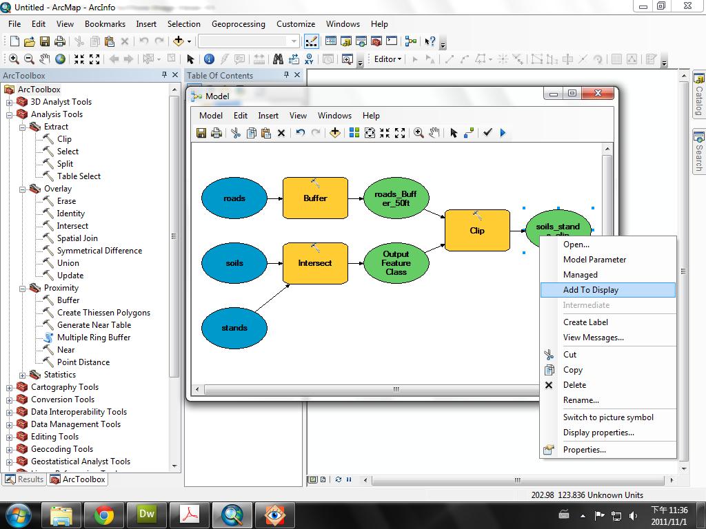
- Right-click on the final output and select Add To Display so
that the output of the model is added to the map display.
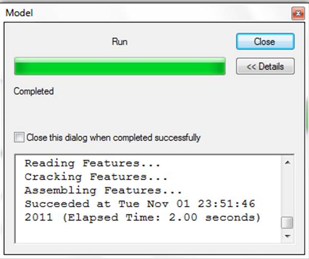
- Now the model is ready to run. Click the Run button
 .
.
The progress indicator will tell you when the process is complete.
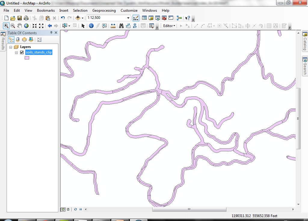
- The new data set will be added to the data frame. If you zoom in you
will see a complex geometry (remember, this is from the combination of
stands and soils).
- Open the table for the new data set.
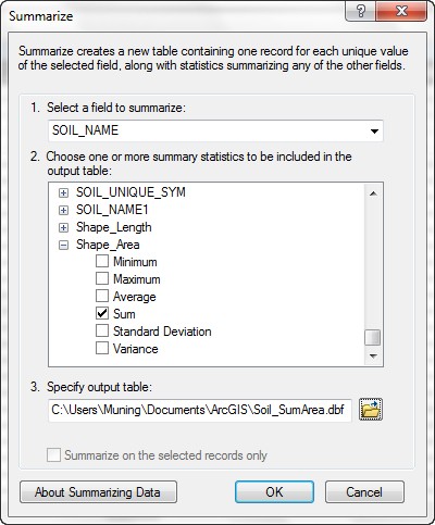
- Create two summaries, one based
on the SPECIES field with the summary statistic Shape_Area >
Sum.
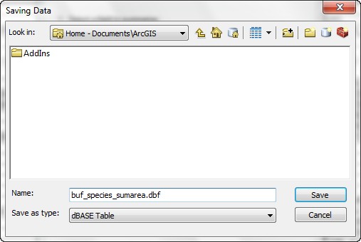
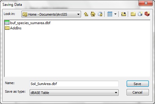
Select the save type as dbase table, put the output table into today's working folder (M:\model_building), the following figures here are the reference.
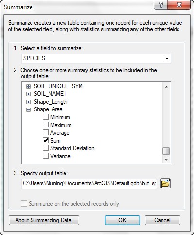
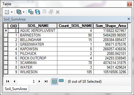
- Also summarize the Soil_Name field.

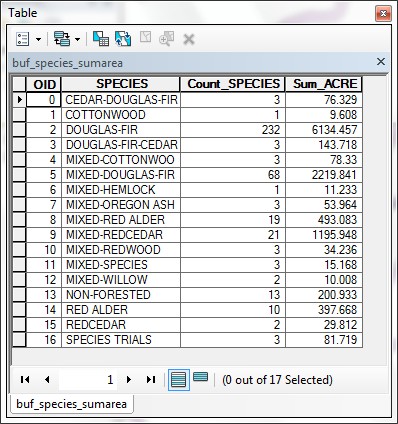
- These tables give you summaries of the area within each SPECIES type within
the buffer zone and the area within each different SOIL type within
the buffer area.
- If you would like to attempt this with variable-width buffers, you will
need to modify the model. Here is an image of a model that joins the buffer
distance table to the roads layer. Give this a try if you want. The parts
to be careful configuring are parameterizing the Add Join tool,
parameterizing the Buffer tool to use the joined field for specifying
buffer distances, and parameterizing the Clip tool so that the
buffers clip the intersected data set (The following figure is the reference from last ArcMap Version, ArcGIS 9.3).
And the output:
The model builder is a powerful and efficient tool which can streamline workflows.
One of the benefits of using the model builder is self-documentation. The models
can be saved and run again, whereas if you simply use a series of manual operations,
it may be difficult to recreate a process exactly. Models can also be placed
within geodatabases or saved as files for distribution. You could bundle a number
of data sources along with a model to allow a collaborator to validate your
methods.
REMEMBER TO TAKE YOUR CD AND REMOVABLE DRIVE
WITH YOU!!!!
Return to top
 |
|
TThe University of Washington Spatial Technology, GIS, and Remote Sensing
Page is supported by the School of Forest Resources
|
|
School of Forest Resources
|
 UW
Home
UW
Home