TAPESTRY: The Art of Representation and Abstraction
How To build a freeform glazing system in form-Z
What is a "freeform window wall"?
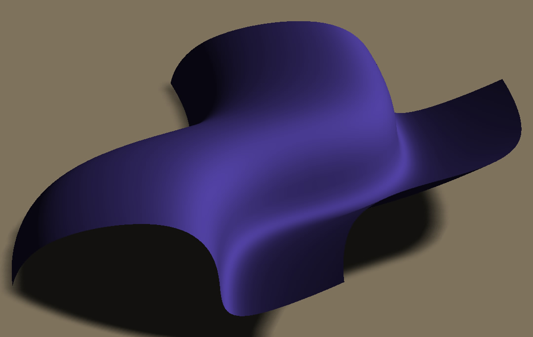
NURBS surfaces permit designers to devise freeform shapes such as the one shown at right, but actual construction requires that various constraints be satisfied. In the best of all possible worlds these would be appropriate geometrical (e.g. planar glass) and material constraints (flexure limits, panel size limits, mullion meeting angles, etc.). form-Z does not permit us to address all of these, but it can help us visualize a panelized solution to a free-form shape. The challenge is creating appropriate approximate geometry.
Step 1: Creating the NURBS surface edges
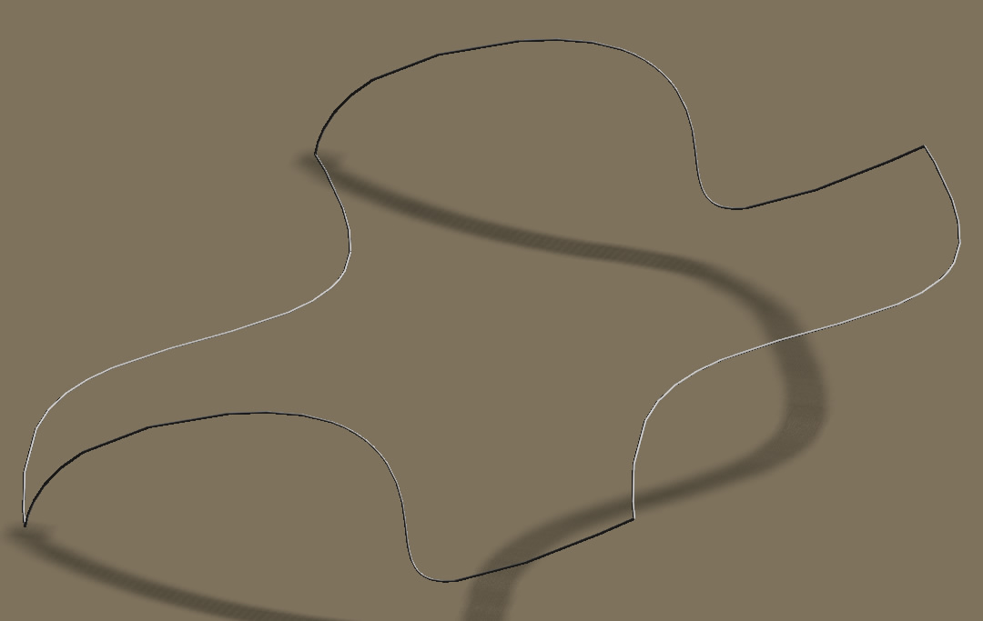
Two cubic-splines were drawn first, one in the XY plane and one in the XZ plane. They were then duplicated and moved, using endpoint snap, into position as shown here, forming the edges of the desired form.
The form chosen here is arbitrary. It is meant to represent a class of forms, in this case ignoring issues of water drainage, edge conditions, etc.
Step 2: Creating the Surface
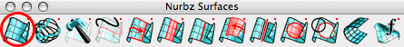
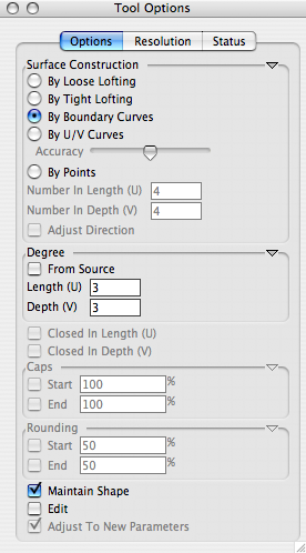
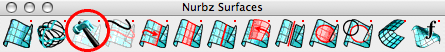
Using the "Nurbz" tool (circled above) from the Nurbz toolbar, and setting the Tool Options as shown at right, we can convert the four curves to a NURBS patch.
Many other form-Z tools may be used to create or manipulalte NURBS surfaces. This is simply the most direct process for this exercise.
Step 3: Manipulate Surface [OPTIONAL]
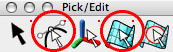
Using the "Edit Controls" or "Edit Surface" options from the "Pick/Edit" toolbar, you could, at this point refine or manipulate the NURBS to improve the result. You might, alternatively, use "Trim/Split" from the "Boolean" toolbar to shape the perimeter of the surface.
However you edit the surface further, at some point you'll want to convert the surface into a form that bears a closer resemblance to elements of construction. There are several different ways to do this. Let's explore a couple of them.
Step 4A: Turning the Surface into Polygons
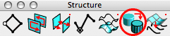
To use the NURB Surface as the definition of a panelized (tesselated) form, we need to convert it to polygons. One tool for doing this is the "Convert" tool in the "Structure" toolbar (circled above). This may be used to "degrade" any geometry from higher-order data to lower, as from "analytical primitive" to "plain", or "NURBZ Surface" to plain. Use it to convert the NURBS surface into it's plain-mesh form.
Step 5A: Adding Mullions
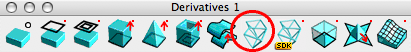
To give the surface a more "greenhouse" look, it might be good to add mullions by "thickening" the edges of the mesh. The "Frame" tool in the "Derivatives" toolbar will do this by forming a tube of a specified radius around the edge.
The "Version A" Result
 The "Frame" tool will make a new object, "Ghosting" the original plain mesh. An easy way to provide glazing for the finished project is to "Unghost" the original mesh and use it, with a suitable surface style, as the glazing. Don't use the original NURBS as this probably doesn't pass through the edges of plain mesh, so your mullions won't meet the glazing right.
Step 4B: Reconstruct the Surface
The "Convert to Plain Mesh" strategy works, but the spacing on the resulting mullions is a bit dense perhaps. How might be get more control over this step? The key is to realize that "Convert" acts to "freeze" the facetted representation of the NURBS into model geometry. By changing the "Display resolution" parameters on the original NURB Surface, we can change the way this is done.
The following ASSUMES you have just completed Step 3.
 Using the "Surface Reconstruct" tool (circled above) you can click on the NURB shape. You should see a dialog box such as that shown at right. The settings on the right-hand side have been changed from their defaults to use "Maximum Edge Length" as the determinant of when to add a new edge. The result of applying this "reconstructions" (and then Converting and Framing, as illustrated above) is shown below.
The "Version B" Result

The panels are more uniform in size, and significantly larger. Alternative values in the Surface Reconstruction process can be used to obtain results 'between' the two shown here. That's it! You've created a freeform skylight, a blobby storefront, or your own draft of the EMP. It's not complete, and it may well have constructability and material issues (like warped glazing surfaces), but it's a start.
Last updated: April, 2014
