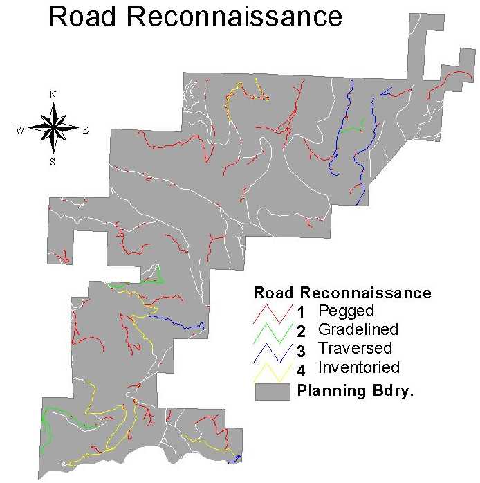
In the Hoodsport block, there were six road systems identified (see Figure 39). The following sections describe each road system and the critical issues that applied to each.
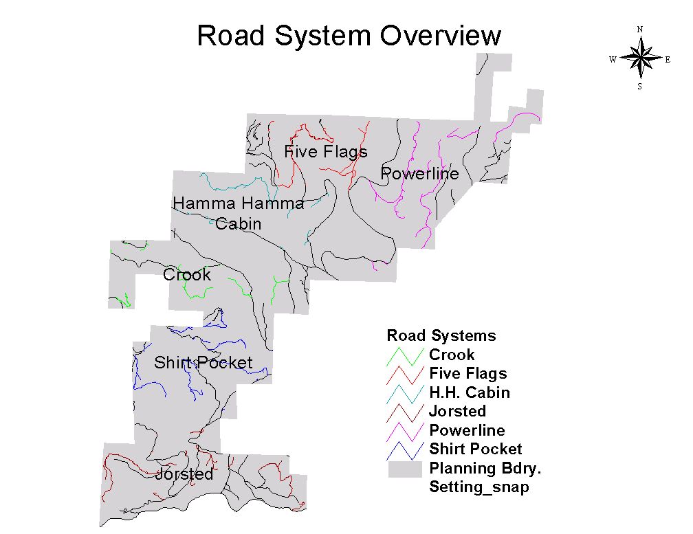
Figure 39 Map identifying the six road systems within the DNR Hoodsport block.
The Power Line road system consists of two sub-systems: the Waketickeh Ridge system and the Power Line Takeoff system. These roads are located in sections 2 and 11 of Township 24 North, 3 West (see Figure 39). This system accesses nearly all of the two sections (approx. 1280-ac) and stretch for a total of approximately 270 stations (approx. 5 miles).
The Waketickeh Ridge system is located along the upper portion of Waketickeh Ridge. The Waketickeh Ridge North and Waketickeh Ridge South sections follow the ridge top from the Forest Service boundary to the north to the end of the ridge in the south while the Waketickeh East Slope Road section drops off the East Side of the ridge to access midslope landings. These roads are accessed from the Web Mountain Road (Forest Service 2510) via the Wicki Ridge sale road, which was constructed in the spring of 1999. From the end of the existing road the access road follows and old railroad grade to a saddle (Sta. 7+36), in the NE 1/4 of NE 1/4 of section 11, on the ridge top where the North and South sections of the road begin.
On the south end of the road approximately 30 station of road which were initially pegged in were not gradelined. These were eliminated in the field verification process due to the steep sideslopes on which the road would be built. The cost of construction under these conditions did not justify the construction of the road. An alternative to accessing the landings that this section of road would have reached was chosen, which accesses the landings as part of the Powerline Takeoff System.
The road begins in the SW 1/4 of NW 1/4 of section 11. The south end of the South section road accesses four proposed landings. To reach some of these landings it was necessary to run a grade of 18% adverse in some areas. This allows the road to stay near the ridge top. Sideslopes on the South section are mostly moderate, being less than 40% in most areas. The exception to this is the extreme southern portion of the road where sideslopes increase to, typically greater than 50%. At Sta. 21+92 a 70-foot radius curve allows traffic to exit the South section of the road system to the Web Mountain Road. This curve is located on a saddle (elevation 1550 ft) in the NE 1/4 of NW 1/4 of section 11. To meet the saddle grades of, typically, 18% favorable were used. There are no stream crossings in this section.
The North section begins at this saddle. This section accesses nine proposed landings on the north portion of Waketickeh Ridge. To keep near the ridge top some steep grades were needed. Grades typically run 13 - 18% favorable. Beginning at the saddle the road climbs at 13% for approximately 15 stations to reach another saddle (elevation 1730 feet). Sideslopes are moderate, typically 35% or less, but increasing near the saddle to 40 - 50%. At this saddle the Waketickeh East Slope Road takes off to the east. From here the road continues to climb at 12% on steep terrain for approximately 15 stations to reach a third saddle (elevation 2000 feet). This area is very rocky with the road running on or near rock outcrops. The route gradelined differs from the original pegged route to avoid having the road pass directly through a rock outcrop for approximately 12 stations. Sideslopes range 45 - 95% in this section. From this saddle the grade slackens to 10% or less with the road staying on or near the ridge top for approximately 7 stations to reach a saddle at elevation 1960 feet. Sideslopes range from flat to steep on this section. From this saddle the grade increases to 18% on steep terrain for another 7 stations to the top of the ridge where another saddle is reached (elevation 2070 feet). Near the top of the ridge sideslopes become more moderate. Continuing north from this saddle the road climbs at 18% for 10 stations on steep terrain to meet the nose of the ridge and the end of the road in the NE 1/4 of NW 1/4 of section 2.
The Waketickeh East Slope Road leaves the Waketickeh Ridge roads at the 1730 foot saddle in the SE 1/4 of SW 1/4 of section 2 to drop down the east slope of Waketickeh Ridge to access four midslope landings. Leaving the saddle the road drops at 18% on steep terrain, with sideslopes of, typically, 50 - 75%, to reach the first landing at station 18+00 at elevation 1430 feet. At Sta. 2+00 the road passes 50 feet above a stream headwall. Two Type-5 streams are crossed at Sta. 10+65 and Sta. 11+50. A stream headwall is crossed at Sta. 12+50. Beyond this landing the road climbs at 12% for four stations then drops at 8% for another three stations then climbing at 11% for a station to reach a second landing at Sta. 26+00 (elevation 1470 feet). Sideslopes are typically steep running 40 - 75% but drop to 10 - 30% near the landing at Sta. 26+00. Two possible Type-5 streams are crossed at Sta. 23+00 and 24+00. From this landing the road continues at 5% or less on moderately steep to steep terrain for 19 stations. There are numerous stream crossings in this area. Three Type-5 streams are crossed at Sta. 32+00, Sta. 38+00 and Sta. 41+50. A Type-4 stream is crossed at Sta. 31+50. At Sta. 45+00 the road comes to an end when it reaches a deeply incised draw in the NW1/4 of NE 1/4 of section 2 (elevation 1580 feet). A landing is proposed at the end of this road. Access to the Upper Boundary timber sale was initially proposed on this route but was abandoned due to the cost of bridging the gully.
Of the landings accessed by this road the landings at Sta. 26+00 and Sta. 45+00 may be eliminated if the areas accessed by these landings are downhill yarded to the Power Line Takeoff Road. This could potentially eliminate the construction of 25 stations of road on steep terrain and six stream crossings.
The second sub-system in the Power Line Road System is the Power Line Takeoff System. Access to this road is from the Hamma Hamma Road (Forest Service 25 Road) on the power line access road. This road has a total length of 113+80 stations and accesses six proposed landings and two proposed timber sales: 2 Tek and Upper Boundary
The road leaves the power line access road in the NE 1/4 of NW 1/4 of section 14 following the power line right-of-way for approximately 15 stations. Grade ranges from 0 - 15% with sideslopes of less than 45%. Leaving the right-of-way at this point the road climbs at 12% for eight stations. Sideslopes range from 0 - 35%. From this point the grade is slacked to 10% to reach a Type-4 stream at Sta. 18+17. Beyond the stream the grade increases again to 12% to meet the original pegged road location at Sta. 30+00. Sideslopes range from 10 - 55% being dominantly below 30%.
This alternate location was chosen over the initial pegged location due to the elimination of one Type-4 stream crossing and construction of road construction on slopes of >30% for the majority of the length of the road. One potential landing in the 2 Tek timber sale was not accessed but it may be possible to put in a spur to reach that landing.
Resuming the pegged road location the road climbs at 4% for seven stations on steep sideslopes ranging from 40 - 70%. The road then continues to climb at 5 - 10% for another 6 stations crossing a Type-5 stream and wet area at approximately Sta. 41+00. Even though the area appears wet there are no signs of soil movement. Here the road splits. One fork continuing up on the pegged location at 5 - 14% on moderate sideslopes reaching a deeply incised draw approximately 16.5 stations from the split. Here this fork ends. The costs of bridging this gully don't justify road construction. Rather a crossing was chosen downstream where the channel is less incised.
The road continues from Sta. 41+00 dropping at 12% to meet the chosen stream crossing. From here the road climbs at 16% to meet back with the pegged location in approximately 18 stations. Choosing this route rather than a lower road location reduces the total number of necessary stream crossings by crossing each stream only once rather than twice, in some cases. From this crossing the road continues to climb at grades from 6 - 16% on moderate to moderately steep sideslopes. At approx. Sta. 95+85 the road forks once more. Continuing on the uphill fork for approx. 4 stations one runs into another deeply incised draw. Crossing here would require a bridge. Access to the Upper Boundary timber sale was initially proposed for this road beyond the draw. This plan was scrapped due to the cost of bridging the gully. So, a crossing is found downstream. The grade is run at 12% to make the crossing. The preferred crossing requires 80’ radius curve and crosses two Type-4 streams. From the crossing the road climbs to a small ridge approx. 2 stations from the crossing. This is the edge of the Upper Boundary timber sale. Here the road forks. The upper fork climbs at 17% for approximately 12 stations to a landing in the upper portion of the unit. The lower fork drops at 10% for 10 stations to reach a bench where a landing could be set to reach the lower portion of the unit.
All of the aforementioned roads have been gradelined and/or traversed.
Other possibilities for accessing the Upper Boundary timber sale would be roads which takeoff from near the end of the road which forks from the Schaerer Creek road in the NW 1/4 of NW 1/4 of section 12 of T24W R03W. The initially proposed road takes off 400 feet from the end of this road in the NW 1/4 of NW 1/4 of section 1. The road proceeded in a northerly direction at a grade of 8 - 18% for approx. 6 stations before running into the first of a number of debris torrents. The road continues on past this to another debris torrent at approx. station 7+50 then on to the proposed switchback location at station 8+00. Upon looking for an alternate switchback location the only possibility was found north of the T24N R03W / T25N R03W boundary. This area is proposed for trading to the Forest Service and so was looked at as "off limits" for this project. The combination of this and the potentially unstable debris flow lead to the scrapping of this proposed road.
The other potential access road for the Upper Boundary timber sale would tale off from approx. 700 feet from the end of the aforementioned road and climb at approx. 10% for approx. 16 stations to reach the lower landing in the unit. From here it would follow the roads which were traversed at the end of the Power Line Takeoff road to access the upper portion of the unit. Sideslopes for this road would be in the 30 - 55% ranges for the majority of this road. There has been no field verification of this route but may be a very viable option for accessing the Upper Boundary timber sale.
The Five Flags Road System can be found in T24N R03W sections 2, 3, 4, 9, and 10 (see Figure 39). This road system consists of four maintenance level roads, the WM-12, K-13, K-16, and K-17 and their associated spurs. This system is primarily centered on the Five Flags timber sale but accesses many surrounding settings. The entrance to the K-## roads is from the Kelly Road (U.S. Forest Service 2572) and the entrance to the WM-## road is from the Webb Mountain Road (U.S. Forest Service 2510). This road system, located in the northwestern portion of the Hoodsport planning area, accesses 1430 acres (2.2 square miles) and extends for 250 stations of road (approximately 5 miles).
The K-13 is an old railroad grade off of the Kelly road. The K-13 road takes off from the Kelly road along an old railroad grade in the NE ¼ of the SE ¼ of section 4 of T24W R03W. This road was planned for access to the Five Flags sale and accesses 209 acres. This road was inventoried along the railroad grade as the planned road follows this for the majority of the length. One disadvantage to this road reconstruction is the number of stream crossings. There are six stream crossings along the extent of the proposed road adding to the cost for rebuilding.
The K-16 and K-17 are existing roads off of the Kelly road in the SE ¼ of the SW ¼ and NW ¼ of the SW ¼ of Section 4 of T24W R03W, respectively. Due to the weather conditions during the field verification portion of the project, the status of the roads was not established. Both roads travel north from the take-off. K-16 is a midslope road with few stream crossings currently in good condition. K-17 travels along the West Side of the ridge midslope with two switchbacks before reaching the top of the ridge.
The implementation of possible long-span yarding from the K-16 road would halt any reconstruction on the K-13 road. This would reduce the amount of road in the area and sediment producing stream crossings. Figure 40 is an example showing the added benefits to long-span yarding by reducing the excessive stream crossings on this road.
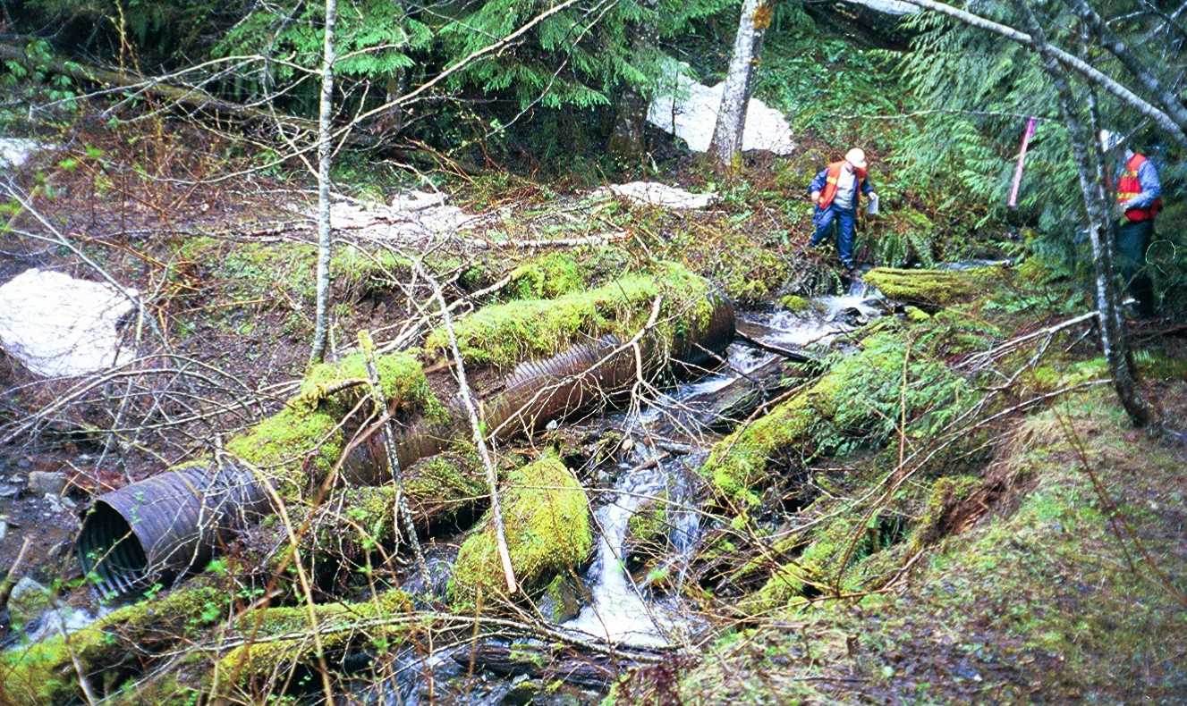
Figure 40 One of the many streams located on the K-13 road. Without maintenance on this road, this stream has bypassed the culvert, adding more sediment from the roadbed to the stream network.
The K-16 road would only access 85 acres if K-13 were built, but would access approximately 206 acres if used as a long span road and K-13 were not built. Figure 41 displays the long-span view from the K-16 road.
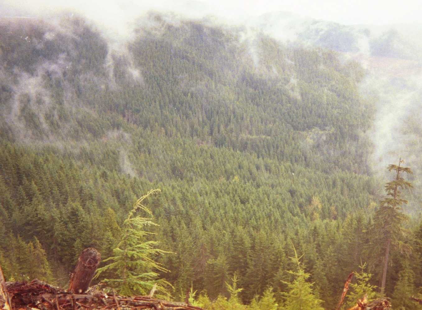
Figure 41 Long-span view from the K-16 road. Using this harvesting alternative will reduce many sediment issues on the K-13 road.
The K-17 road accesses XX acres, but only contains two usable tower landings that do not cover the entire area and the topography for the remaining area surrounding the road is too steep for using a swing yarder. An option with this road could be to decommission almost 2 miles of road and use a helicopter system for harvest. This would reduce the road density and potential sediment production in the area.
The WM-12 road is the only new road planned for this area. This road has not been gradelined due to the time constraints of the project and the other priorities set by the DNR. It is located predominantly in topography of low gradient (slopes less than 30%). There are different alternatives for this road. This road accesses 380 acres. The proposed road, including alternatives, takes off from Webb Mountain in the NW ¼ of the NE ¼ of Section 10 of T24N R03W, which is approximately ¼ - ½ mile below the new road constructed for the Wiki Ridge timber sale. The road slowly climbs northerly at 8% for approximately 9 stations where it branches off in two alternatives. These alternatives are referred to as WM-12a and WM-12b with similar grades for each option, where the road can cross Waketickeh creek in two optional locations upon field verification of the best crossing. At the reconnection of these two alternatives, the road advances in two different directions. WM-12a travels southwesterly for 12 stations and then westerly for 15 stations with moderate grades between 0% and 8%. WM-12b travels below a slightly steeper portion of ground in a northerly direction for 19 stations with grades between 6% and 10% and then continues slightly more west as WM-1211 for an additional 20 stations with similar grades. Another option existing on this road is WM-121. This option begins where WM-12b turns into WM-1211 and travels southwesterly, above the steeper section from WM-12b for 27 stations with grades ranging from 5% to 8%, joining WM-12a 10 stations past the initial creek crossing. Originally the WM-1211 reconnected with Webb Mountain road approximately 10 stations before the U.S. Forest Service border, but contained a switchback located in Forest Service land. After speaking with the DNR and additional analysis of landing and setting locations, the road was terminated at the current location.
The current extent of the road is under consideration for building the road for ground and swing based harvest systems. If the roads were not built and harvested with a helicopter system, this would reduce the impacts on the Waketickeh creek.
11.4.3 Hamma Hamma Cabin System
The Hamma Hamma Cabin Road System can be found in T24N R03W sections 4, 8, 9, 10, 15 and 16. This system was deemed ‘low-priority’ and therefore not field verified. It accesses 1,859.3 acres (2.91 sq. mi.) of timber including the Horse-Webb sale and several surrounding alternative sites with approximately 193+92 stations (3.67 miles) of planned roads and spurs.
However, we have been recently informed of an owl circle that covers almost the entire harvestable area of this road system. Therefore, this system can not be utilized for approximately the next 10 years. At that point, it may be possible to reevaluate the situation and implement this design.
The Crook Road System is located in T24N R03W sections 16, 17 and 18. The system is relatively straightforward and was not field verified. The system accesses 1043 acres (1.63 sq. mi.) of timber with approximately 198 + 00 stations (3.75 mi.) of planned roads, including spurs.
The system consists of four roads with the Crook Road (FS-191) being the only road of interest. It is located in an area with many streams, and the initial office design contained three crossings over type three streams, and three crossings of type five streams. After a major redesign of the Crook Road, two of the type three stream crossings were eliminated, and one type five crossing was eliminated. In addition, the overall length of the Crook Road was reduced from 80 stations to 57 stations. Most of this road is located on side slopes of less than 30%, so there is a lot of flexibility for selecting a suitable road location in the field.
The Shirt Pocket Road System can be found in T24N R03W sections 16, 17, 19, 20, and 21. The system is primarily centered on the Detached and Alien sales and accesses several surrounding alternative sites. This road system consists of six individual road segments and the usual associated spurs. Of these segments, only one would be considered a major road or classified as ‘mainline’ while the rest would be considered strictly ‘management’ class.
In this system there is approximately 345 + 00 stations (6.5 miles) of designed or planned roads. The majority of these may or may not be used depending on whether alternative sites for harvesting are investigated. This system allows access to about 2,000 acres (3-sq. mi.) of timber, including both the Detached and Alien sales.
The Shirt Pocket Road System includes two roads of significance, identified by the DNR—the Shirt Pocket Road (FS-15) and the Hook Road (FS-146). The Shirt Pocket is significant because it serves as a bypass for the Wes Road, which is currently out of commission. The Hook Road was identified, as ‘of interest,’ after others of higher priority were deemed unreachable due to the weather conditions.
The Wes Road that has historically accessed this area currently requires the replacement of two bridges. While one bridge is feasible, the northernmost crossing is irreparable based on our field reconnaissance (see Figure 42 below). Therefore, a bypass is a desirable alternative allowing for the access of local sales and moreover the efficient transport from further north. A bypass could potentially alleviate both costly bridge constructions, if not at least one.
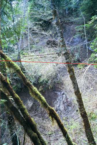
Figure 42 Road failure on the Wes Road, along the northernmost stream crossing requiring a bridge. The red line indicates the approximate location of the road grade, which has failed and is now down below in the stream. Steep upslope conditions along the failure plane will not allow for the reparation of this segment.
The Shirt Pocket Road branches directly off of the U.S. Forest Service 2480 Road in the SE ¼ of the SW ¼ of Section 21 of T24N R03W. The road climbs gently in a northwesterly direction for approximately 58 + 00 stations, through the Alien sale, then reconnects with the Wes Road. The initial gradeline was run at about twelve percent while the side slopes were typically less than 40 percent.
The Shirt Pocket Road was fully designed. In the field you will find a primarily orange gradeline. The P-line was done in primarily blue and pink. The road was also fully traversed. Flashers and paint mark the reference trees locating the centerline.
The initial design was changed due to a very large gorge channeling a type-5 stream. The location of the gorge was about 40 + 00 stations in along the gradeline. A suitable crossing was found upstream, and the gradeline was adjusted accordingly (i.e., 14-16%) to tie in quickly with the original gradeline. After the gorge the road climbs at about 12% up to the existing Wes road. The connection happens north of both crossings on the Wes Road requiring bridges. Therefore, the Shirt Pocket bypass eliminates the need for bridge construction. There are draws with type 5 streams that will require significant fill for an adequate crossing. However, the cost associated with this road and its long-term stability make more advantageous, by far, than the alternative of reconstructing the second crossing of the Wes Road.
The Hook Road takes off from the Wes road in the SW ¼ of the NW ¼ of section 20 in T24N R03W. The Hook Road is significant because it accesses key vantagepoints along a ridge top for future alternative sales. However, the Wes road crosses into Manke property for a stretch. The Hook Road is a ridge top road that meanders in and out of saddles on the ridge. The micro-topography of the area is peculiar and of note. There is a rock outcrop approximately 50 + 00 stations in on the gradeline.
The Hook road is not fully designed. In the field you will find the gradelined flagged in orange. The maximum adverse grade was 15%. The maximum favorable grade was also 15%. The average road grade was 8%. Sideslope percentages ranged from 5-90% with an average of about 40%.
There are several other segments in this system. However, have only been planned on paper and not in the field. All of these roads are proposed locations. None of them have been flagged or walked at the present time.
The Jorsted system can be found in portions of Township 24 North, Range 03 West, Sections 29, 30, 31, 32, and 33. This system is located just north of the Jorsted Road (FS-24). The most important segment of this system is the bypass of the Jorsted Slide. There are three other major roads in this system, all would be classified as management roads.
This system is composed of approximately 316 stations (5.98 miles) of designed and planned roads. These roads will access just over 1700 acres (2.71 sq. mi.), which will include the Jorsted sale.
The Jorsted Bypass (J-11) was designed to allow more direct access to Highway 101 from areas in the southern portion of our planning area. This road is an alternative to reconstructing FS-24. The estimated cost for reopening the slide area is $1.1 million. The cost sharing agreement between the DNR and the USFS is 60%-40% respectively. This equates to a cost of $630,000 to the DNR if this road is reopened. The estimated cost of the Jorsted Bypass road is approximately $64,000. Along with a lower construction cost, the bypass road is located on more stable ground, which will require less maintenance over time.
The second major road in this system is the Dynamite Ridge road (J-2322). This road is located along the ridge top and will replace approximately ½ mile of existing midslope road. This road accesses about 10 sales, most of which will be harvested after period 5 of this 25 year plan. This road was gradelined and p-lined. The critical design point on this road is the rock outcrop located at station 39+00 and 44+00.
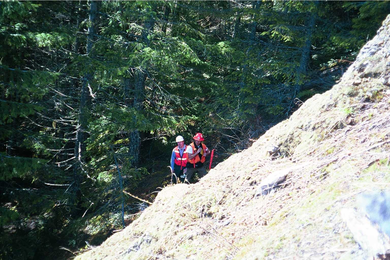
Figure 43. Looking ahead on gradeline from top of rock outcrop at 44+00
While p-lining this road we tried to get above the outcrop at 44+00 and in doing so the alignment shifted heavily into the outcrop at 39+00 (See Figure 44). Due to time constraints we were not able to realign the p-line at this segment but we do suggest that before this road is traversed, to adjust the p-line (blue flagging) such that it follows the gradeline (orange flagging) as closely as possible.
Figure 44. Rock outcrop at Station 39+00
The roads that will access the Jorsted timber sale were planned and field verified by the DNR staff in Hoodsport. This sale is part of the DNR’s 5-year action plan that we received at the start of this project. We did not feel that this system needed any further analysis.