
Introduction to Geographic Information
Systems in Forest Resources |
Exercise: Creating
Feature Datasets & Vector Editing
Objectives:
- Creating new feature layers by query of existing feature layers
- Digitizing a new layer from scratch
- Perform drive
substitution to create drives L (CD) and M (removable drive).
- Start ArcMap and open an existing map document
- Query a layer to select a subset of features
- Convert the selected set of features to
a shapefile
- Create a new feature class in the geodatabase and modify its legend
- Set the snapping environment
- Add features and attributes to the new layer
- Edit features with Split and Union
- Stop editing and save your edits
- Create a new point layer
- Create a new line layer
- Create a stands polygon layer
- Close the map document
Perform drive substitution
Perform drive
substitution to create the virtual drives L and M.
Start ArcMap and open an existing map document
- Retrieve the map document create_f_layer.mxd.
Save it in your personal directory.
- When the create_f_layer.mxd map document opens, you will see a data
frame containing two layers.
Query a layer to select a subset of features
Forest thinning operations typically occur early in the life cycle of a forest
stand. In this exercise, create a feature class from the stands (ArcInfo
coverage) layer, consisting only of stands between the ages of 15 and 30.
- From the menu, select Selection > Select By Attributes. The dialog
will open.
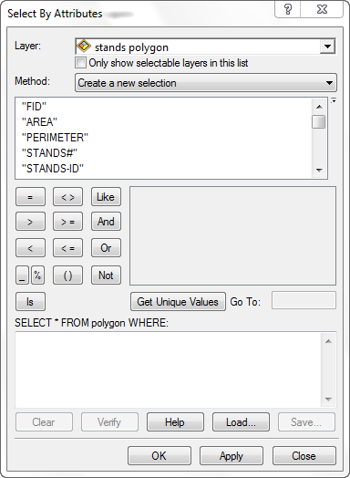
- Make sure the Stands layer is selected. Leave the checkbox unchecked,
and leave the default choice for Method.
- Perform a query to select stands between the ages of 15 and 30:
- Double-click AGE_2003 in the list of Fields: (do not mixed with the AGE_CLASS_2003).
- Click the greater-than button (
 ),
and type in the number 15.
),
and type in the number 15.
- Single-click the and button (
 ).
).
- Double-click the AGE_2003 field.
- Single-click on the less-than button (
 ),
and enter the number 30.
),
and enter the number 30.
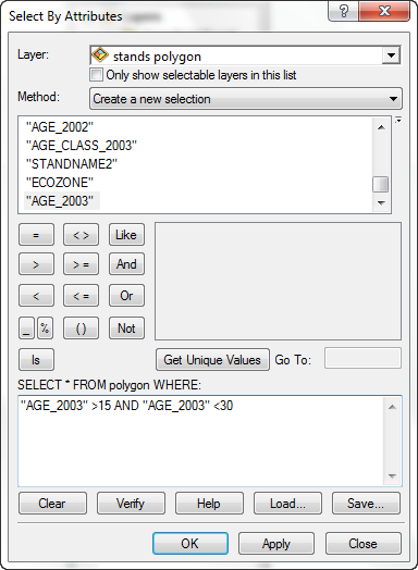
Note that the select statement reads SELECT * FROM stands.polygon WHERE:
"AGE_2003" > 15 AND "AGE_2003" < 30.
Also note that the Method is Create a new selection, which will ignore any existing selections, and select all records matching the query conditions.
If your select statement reads differently, delete the contents of the
expression control and enter the data again.
- Click the Apply button, and dismiss the dialog.
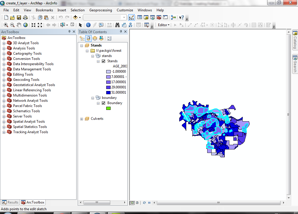
- The layer will show stands that meet the selection criteria outlined in
a thick cyan symbol.
You have just selected a set of features from a polygon layer. You will use
this set of features in the next step to create a new layer composed of only
these features.
Convert the selected set of features to a shapefile
- To convert this selected set into a shapefile, right-click the layer's name
and select Data > Export Data.
- Save the data set as stands_15_30 in your Geodatabase on the M drive (keep the default
Coordinate System choice).
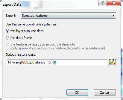
You will see the Export Progress dialog.
- Click Yes when asked to add the shapefile to the data frame.
- Turn off the original stands layer. Your data frame should appear like this:
- The new layer is composed of only those polygons matching the query criteria.
You have just taken a set of selected features and created a new shapefile
composed of only those features. Use this technique whenever you want to create
a subset of features from a layer. Sometimes you need a smaller dataset for
a specific spatial area, or a set of features that has a specific attribute
value.
Create a new feature class in the geodatabase and modify its legend
Next, create a new layer that will represent four different culvert management
units. Each management unit will be used to schedule routine annual inspection
and maintenance of culverts on the forest.
- Activate the Culverts data frame.
- Click on the side menu and open ArcCatalog by clicking the ArcCatalog button
 .
.
- Navigate to your geodatbase (last exercise) -- M:\NETID.gdb within ArcCatalog.
- Right click the geodatbase, and select New > Feature Class from
the menu.
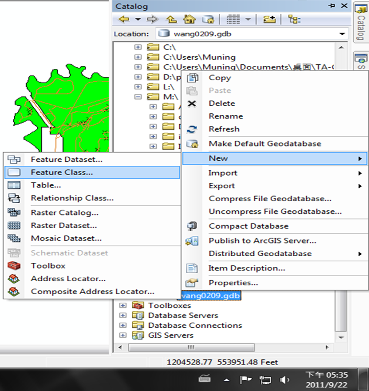
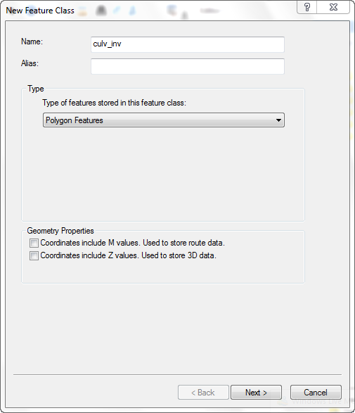
- Call the new shapefile culvert_inv (for "culvert inventory").
Select Polygon as the Feature type.
Click NEXT to enter next setting. You can choose your projection in next page.
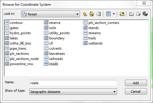
- It will be important to have the new shapefile in the same coordinate system
as the other data. Define the new shapefile's coordinate system to match the
existing roads. To do so, find out the grey globe symbol on the top (named Add Coordinate System), and click Import and navigate to L:\packgis\packgis.mdb\forest, click
roads, and click Add. This will copy the projection parameters from the roads data set onto the new data set. After that, the Spatial Reference Properties will be updated.
- Click NEXT until it finished.
You can see the new feature class within your geodatabase in ArcCatalog.
- Also, it will be insert to your ArcMap automatically.Now you should see the new layer from Table of Content. DO NOT Click "Full Extent" since the new layer is empty and ArcMap will not be able to zoom in all the layer properly.
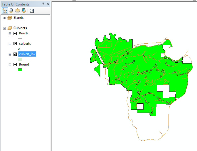
- Change the layer's symbology by clicking on the symbol for the layer.
- Change the Fill Color to No Color, the outline width to 2,
and the Outline Color to a bright red. This way new polygons will appear
clearly without obscuring underlying layers.
You have just created a new (empty) polygon shapefile. The legend was also
changed to a transparent symbol so that you can see underlying features.
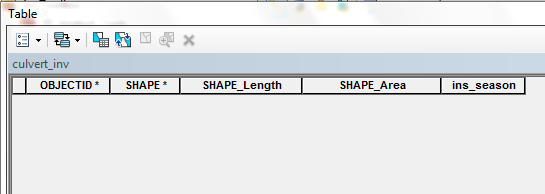
Alter the attribute table
- If you want to have your own attribute fields, these need to be added to
the attribute table. Right-click the layer and select Open Attribute Table.
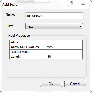
- Select Options > Add Field.
- Call the new field ins_season (for "inspection season").
- Select Text as the data type
- Enter 10 for the field length.
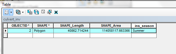
- Now the attribute table has a new attribute, but still no records exist.
When polygons are added to the layer, records will automatically be generated
for each polygon feature. To add a new record, you need to enter the values after opening the "Editing Tools". You won't be able to add a record without activating editing tools. Also, any records should be added after adding
a new feature within the layer.
- Minimize (but do not close) the attribute table.
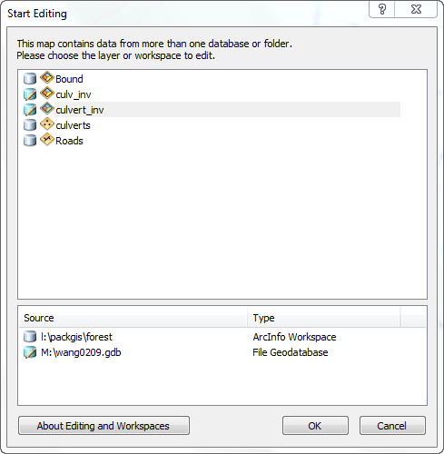
Start editing
- Click the Editor toolbar buttom
 is next to scale bar from
the menu.
is next to scale bar from
the menu.

- Dock the Editor toolbar in the ArcMap GUI.
- To start your edit session, select Start Editing from the Editor
toolbar's Editor menu.
Set the snapping environment
Snapping is an important control in the environment. It will assure that features
snap to each other, and that dangles, overshoots, gaps, or slivers are avoided.
- The Snap Tolerance tool will allow you to interactively define a
snapping distance. Add the Snap Tolerance tool to the editing toolbar.
To do this, select Customize from the Tools menu.
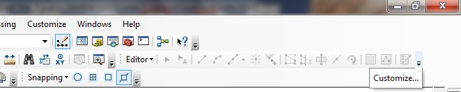
- Find the Editor Category and the Snap Tolerance Command.
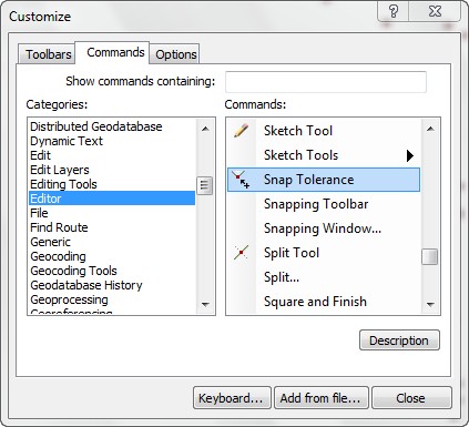
- Drag the Tool directly to the Editor toolbar.
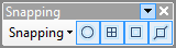
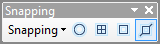
- To specify the snapping environment, select Snapping Toolbar from the Editor
menu. Note that you have control over what geometries will snap. This means
as you add features they will "snap" to either vertices, edges,
or ends of existing features. Original Setting has all snaping featurs.
- Click Start Editing from the Editior Toolbar.
- Click the Snap Tolerance tool
 ,
click and drag a distance as your snapping tolerance. When features are added
that come within this distance of existing features, snapping will occur.
,
click and drag a distance as your snapping tolerance. When features are added
that come within this distance of existing features, snapping will occur.
Setting the snapping tolerances is important to set before you start editing
line or polygon features. You can always reset snapping tolerances at any time,
based on the precision you need.
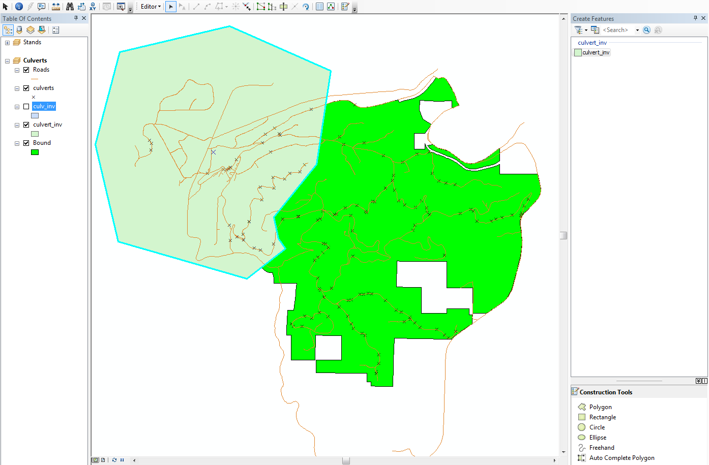
Add features and attributes to the new layer
- If you are opening the editor tools, select "Start Editing", and you need to select which target to edit. Select culvert_inv layer and the pop-up window will start the editing window to add new features.
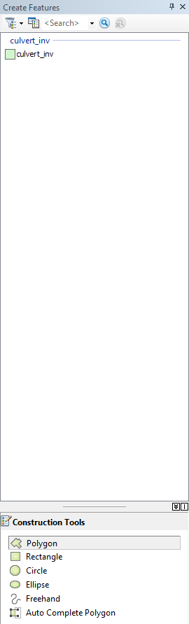
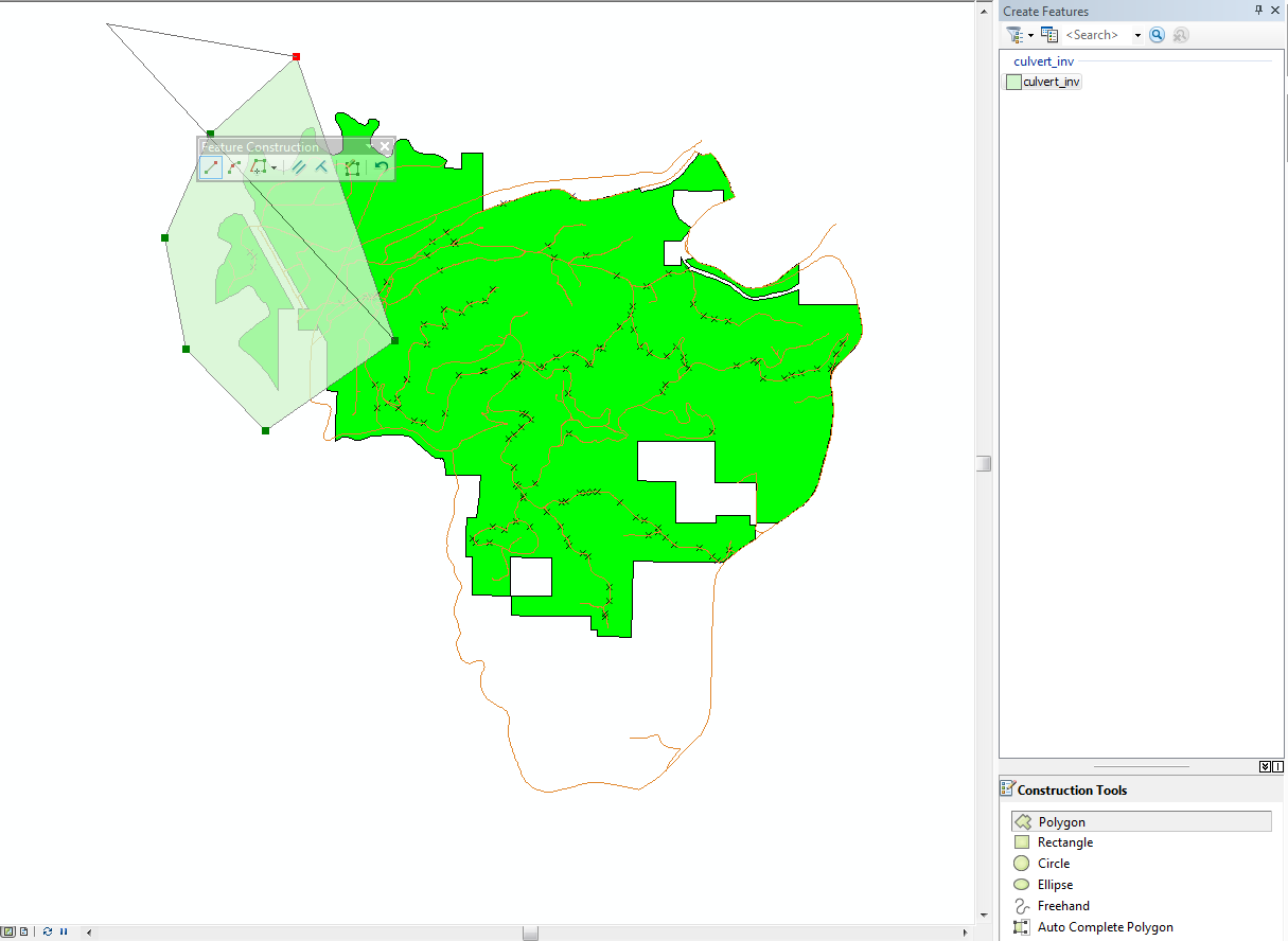
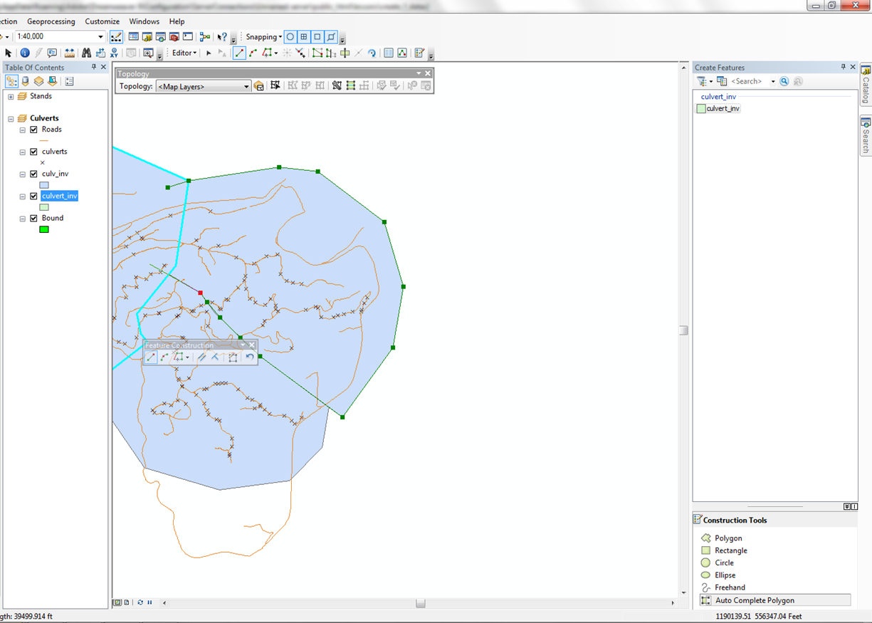
- Click on culvert_inv at the "Create Features" window and you can start to create your first polygon. On the map, you can start to click the vertex to draw a polygon outline.
When the polygon has the shape you want, double-click
(or use the <F2> key) to end the polygon. Make sure that the
outer edges of the new polygons go completely outside the Pack Forest boundary;
we will clip the management units later to match the forest boundary.
After the polygon feature is added, you will see it selected with the default
selection symbol. To select a feature while in edit mode, use the Edit tool  and click
on the feature's edge. If the polygon is incorrect, press the <DELETE> key to remove it.
and click
on the feature's edge. If the polygon is incorrect, press the <DELETE> key to remove it.
- Next, make the table active, double-click in the ins_season cell for the selected record,
and type Summer.
-
The next steps will be to add new polygons with the auto-complete option.
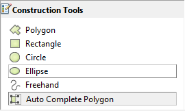
You should never attempt to digitize over existing edges, because it is likely
you will be creating gaps or slivers. Auto-complete is part of the topology
tools. To access the topology,
right click on the mouse from the menu, select the
Topology toolbar and dock
the toolbar near
Editior Toolbar.
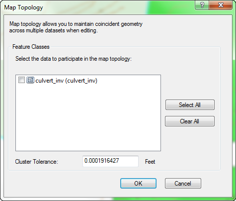
- From the Topology toolbar, click the Map Topology tool
 .
Click the checkbox for culvert_inv. In this editing session, this will
be the only layer participating in the topology. Click OK.
.
Click the checkbox for culvert_inv. In this editing session, this will
be the only layer participating in the topology. Click OK.
- Alter the Task to Auto-Complete Polygon.
- Add a new adjacent polygon by making the first click within the existing
polygon, then move outside the existing polygon, adding vertices as needed.
To finish the new adjacent polygon, double-click again within the first polygon.
Do not attempt to return to the starting node of the polygon, just click inside
the original polygon as shown below. Any overshooting lines will be automatically
dropped, and the common boundary will be duplicated.
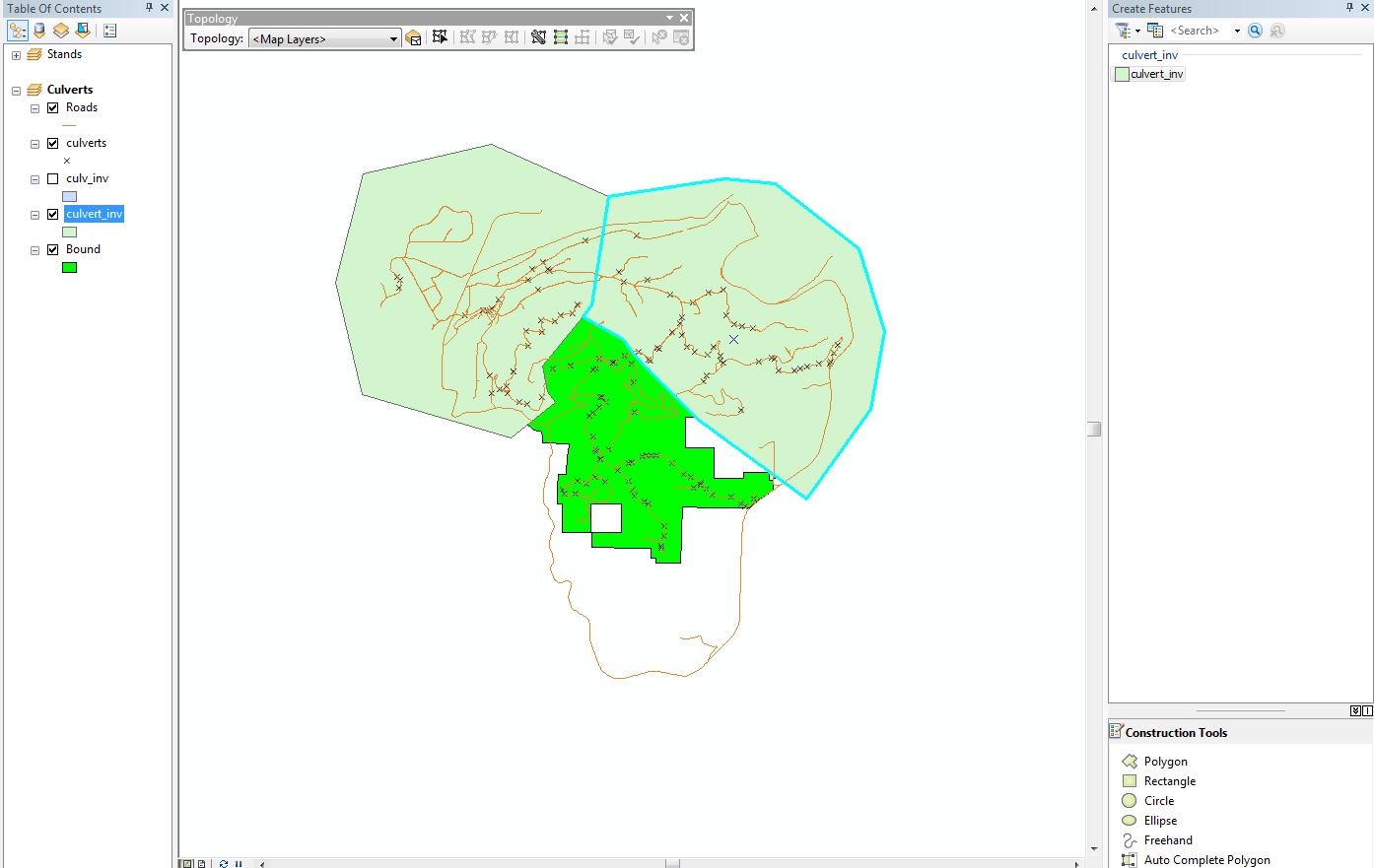
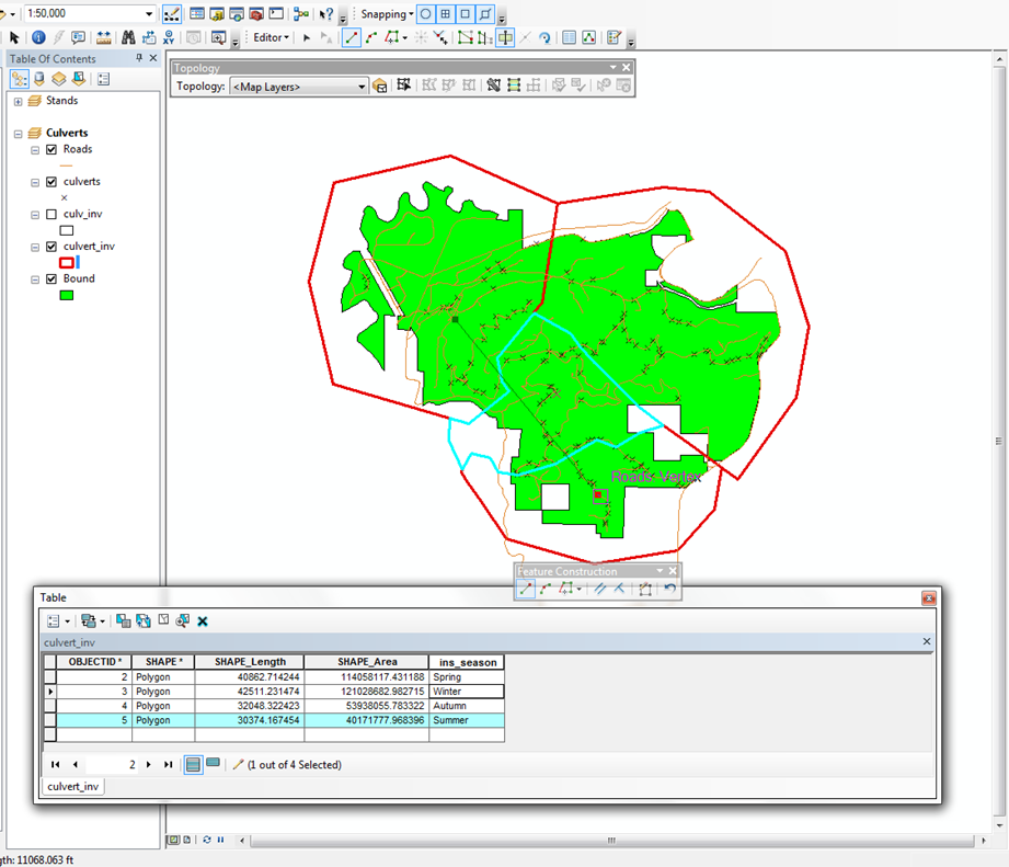
- Each time you add a polygon, it will be selected. Update the records for
each polygon as they are added. You may need to Options > Reload Cache
in the table, or close and reopen the table in order to see all the records.
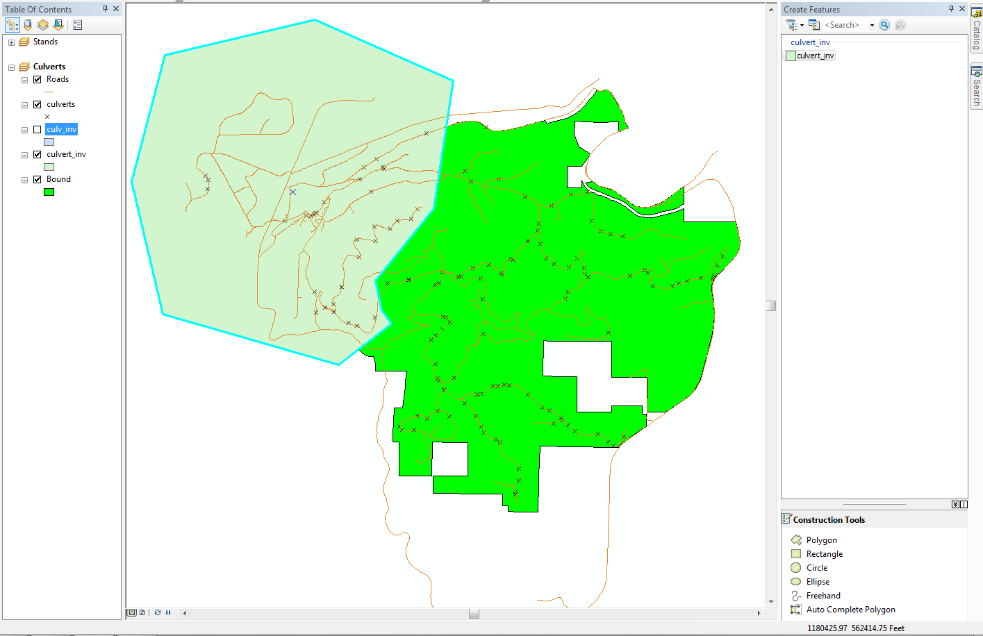
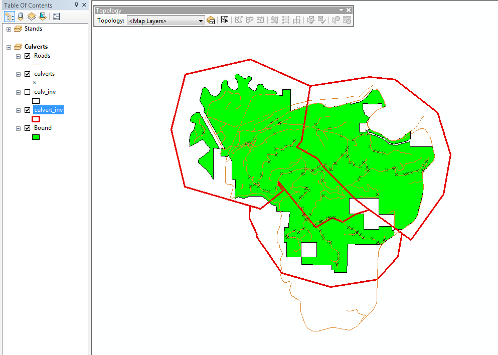
You should end up with an application looking similar to this:
You have just added several polygon features to a new polygon layer. Especially
important is using the Polygon Auto-Complete tool, which will allow
you to create new polygons that are adjacent to existing polygons, without needing
to retrace the common boundary.
Edit features with Split and Merge
Suppose that now it has been decided that Summer is too busy a season to perform
culvert maintenance. Therefore, the Summer polygon must be split up and
merged with adjacent polygons. Some of the culverts will be placed in the Autumn
polygon, and some in Spring.
- First, save your current edits (Editor > Save Edits) and File
> Save.
- Select the record in the table for the Summer polygon. You can select
the record by clicking the record in the untitled column to the left of the
FID field.
You will see that the polygon is selected. In order to split a feature it
is necessary for the feature to be selected.
- Change the Task to Cut Polygon Features. Define a line that
splits the polygon (making sure to start and end outside the selected polygon).
Double-click or <F2> to end the line.
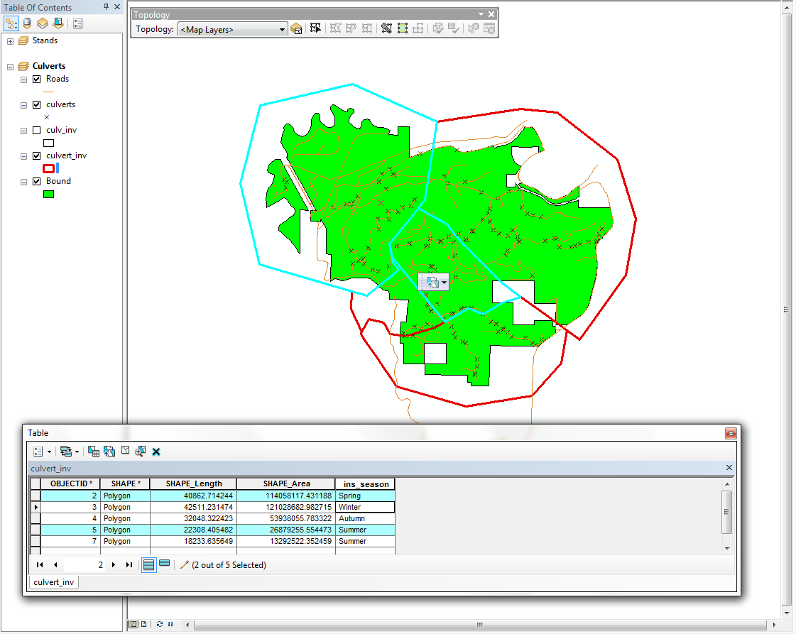
- Use the Edit tool
to select half of the split polygon and an adjacent polygon (click on the
outline to select). Use the <SHIFT> key to select more than one
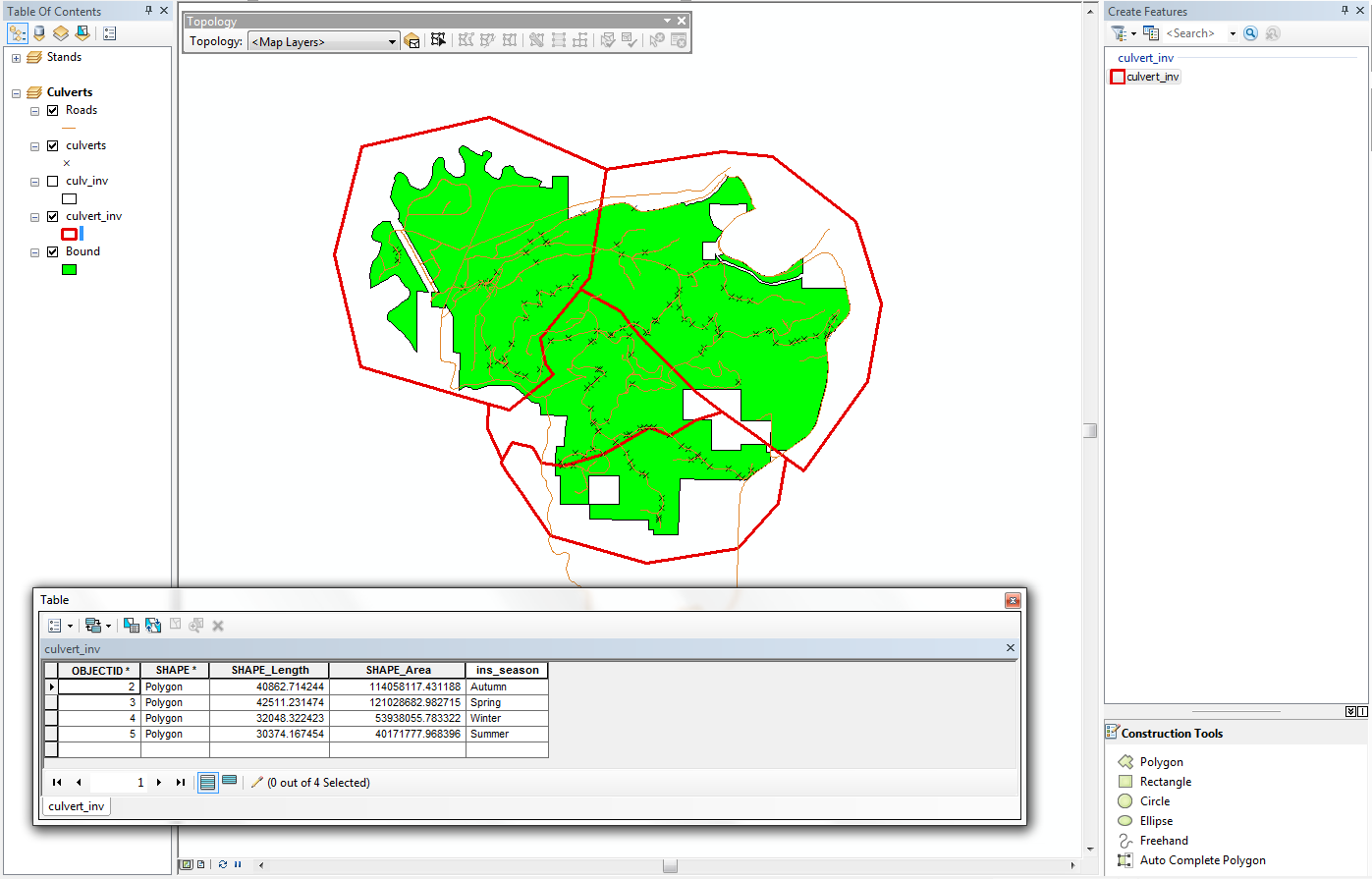
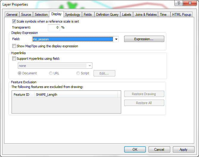
polygon. Keep the table open, you will see your selection is at the right season (Spring & Summer in the following figure). Also, change the display field in the layer propertities (right click on the layer and select propertities, in the display section) to ins_season
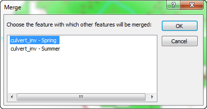
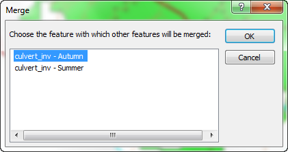
- Select Editor > Merge to merge the two polygons together. Make
sure the non-Summer polygon is selected (you want to merge the piece of the
Summer polygon with the other polygon).
- Select and merge the other half of the Summer polygon with its adjacent
polygon.
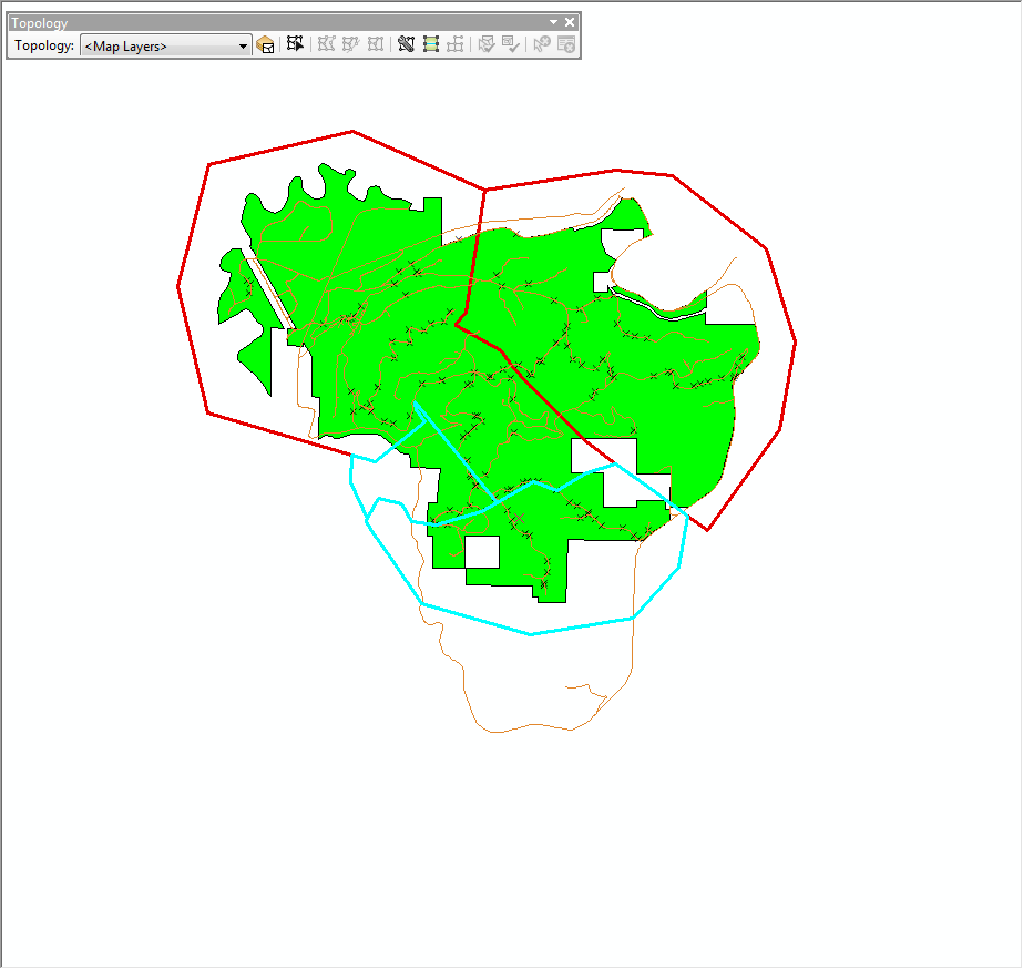
- The new polygons should look something like this:
- If the attribute values are not correct, select the erroneous polygon(s),
and edit records if necessary.
You have just used splitting and merging to alter the coordinate and tabular
parts of the layer you created in the previous task.
Splitting and merging polygons can be used when areas or patches change shapes
or size. For example, if a set of contiguous forest stands is harvested, it
may be unioned a single new stand. If a single forest stand develops different
characteristics over time, it may be split into several different polygons.
Stop editing and save your edits
- When you are satisfied with your edits, select Editor > Stop Editing.
Click Yes in the Save dialog.
- Note that any changes made to the shapefile are saved to the disk. If this
layer is added to another data frame or map document, it will open in the
same state in which it was saved.
Save your changes frequently, even if you do not stop editing. It takes a lot
less time to stop and save your changes than it does to recreate a dataset in
case ArcMap crashes during your editing session (note that this happened to
me while creating these instructions!).
Create a new point layer
Creating point layers is similar to (but less complicated than) creating polygon
layers, except that point and line graphics tools are used, rather than polygon
editing tools. Attribute tables are altered in exactly the same manner.
- Create a new data frame. Rename the data frame from Crossings.
- Add the feature classes roads and streams, from the geodatabase L:\packgis\packgis.mdb,
and into the feature dataset forest.
- Create a new feature class (as you did before), but this time make it a point
data set and call the feature class crossings. Import the coordinate system properties as you did before (from one of the data sets in L:\packgis\packgis.mdb\forest).
- Add the crossings feature class to the data frame. Open the attribute table for the crossings point layer and add the
fields Stream (type = text, length = 25) and Road (type = text,
length = 25). This will be used to hold the stream and road names for each
crossing.
- Start editing the data. When you start editing, select the right geodatabase (M:\NETID.gdb) to start editing.
- Alter snapping to snap ONLY
edges of roads and streams (unclick other snap options).
- At the Create Features window, click on the crossings layer to start editing.
- Open a magnifying viewer (to see a small part of the data frame at a larger
scale) by selecting Window > Magnifier from the menu. Alter the
snap tolerance if you are not snapping to features. In order to see your snap
tolerance, you can keep the <t> key depressed.
- When the pointer snaps to a crossing, add a point. In order to find which
road and stream where this crossing is located, use the Identify tool
 .
Make sure the layers that are identifiable are <Visible layers>.
Click the road and stream to find identifiers. If there is no stream or road
name, then these values can be blank for the point record.
.
Make sure the layers that are identifiable are <Visible layers>.
Click the road and stream to find identifiers. If there is no stream or road
name, then these values can be blank for the point record.
- Update the point record for the values:
For the point I chose, there was no name for the stream, so I left the value
blank.
- Move the magnifier window to a different crossing location. Repeat the process
above for a few more points. You get the idea....
- Stop editing and save changes (From the Editor toolbar, select Stop Editing)..
Create a new line layer
- Create a new data frame called New Roads.
- Create a new shapefile (M:\NETID.gdb\new_roads). Make sure this is a Polyline
feature class. Import its coordinate system parameters from the roads geodatabase
feature class in packgis.mdb\forest.
- Add the \packgis\forest\ortho_96.bil image data source and the roads
feature class from the L:\packgis\packgis.mdb\forest.
- Zoom into the area outlined in yellow in this image:
- Add the new shapefile to the data frame.
- Start an editing session. If the Start Editing selection is not available in the Editor toolbar, you are probably still editing in the Crossings data frame. If so, make the Crossings data frame active and stop editing, then make the New Roads data frame active and start editing.
-
Set the Snapping environment (keep original setting) and reset the snapping tolerance if necessary
- Zoom in and start creating some roads based on what you see in the image.
- Continue adding a few other road segments. Here is a location for another
road:
You may need to zoom in and out as you add features, or use the magnifier.
- Stop editing and save your edits.
Create a stands polygon layer
- Create a new data frame called Stand Digitizing and add the same
orthophoto image layer you added in the last step. The easy way to do this
is right-click on the orthophoto in the New Roads data frame, and select
Copy. Then right-click on the Stand Digitizing data frame and
select Paste Layer(s).
- Add the boundary layer and alter its legend to make it unfilled as you did
before with the culvert inventory polygon layer
- Create a new polygon feature class called stands. Import the coordinate
system parameters from the roads data set.
- Add 2 fields (Origin_yr [type = short integer] and
Species [type = text, length = 4]).
- Zoom into the portion of the forest shown below:
- Now you should see some clearly visible stands and recent cut units.
- Add the new stands shapefile to the data frame and alter its symbol.
- Start editing. If you get a warning, dismiss the dialog.
- Enable snapping and set the snap tolerance.
- Set the topology as you did before, which is necessary to perform auto-completion
of polygons.
- Draw a polygon using the Sketch tool.
- Update the attribute values for this polygon (Origin = 1955, Species = Douglas-Fir [Pseudotsuga menziesii]).
- Using the Auto-Complete Polygon task, create an adjacent stand.
- Update the values for this polygon's record as well (Origin = 1930, Species
= Western hemlock [Tsuga heterophylla])
- Add a third polygon
- Alter the record by right-clicking on the shape with the Edit tool
and selecting Attributes.
Update the values (Origin_yr = 1940; Species = PSME):
- You have just found that one of the stands needs to be split, and part of
that stand merged with an adjacent stand. Select the northwestern stand of
the group of 3 and split it into two pieces using the Cut Polygon Features
task.
Note that the record has also been split:
- Use the Edit tool to select the northernmost and easternmost 2 polygons
(use the <SHIFT> key for making multiple selections).
- Before performing the merge, change the Display Field to
Species from the layer's properties (Display Section).
- From the Editor menu, select Merge Features. You want to merge
the PSME polygon with the TSHE polygon.
You will see that your polygons have been merged, and the records have also
been merged.
- Continue to add more polygons and records if you have more time left to
get more practice.
- Stop editing (Editor > Save Edits and Editor > Stop Editing)
and save your edits.
You have just used a digital orthophoto image as a backdrop for creating two
new vector datasets (roads and streams). There are a large number of digital
orthophotos for Washington state available from the Map Collections in Suzzallo
library. Additionally, the WA Department of Natural Resources maintains a large
collection of digital orthophotos that can be purchased directly from the DNR.
Close the map document
Save the map document and then close the ArcMap Session.
REMEMBER TO TAKE YOUR CD AND REMOVABLE DRIVE
WITH YOU!!!!
Return to top
 |
|
The University of Washington Spatial Technology, GIS, and Remote Sensing
Page is supported by the School
of Forest Resources
|
|
School of Forest Resources
|
 UW
Home
UW
Home