Introduction to Geographic Information Systems in Forest Resources
| Introduction to Geographic Information Systems in Forest Resources |
|
|||||||||||||||
|
|||||||||||||||
Most of the projects you will encounter will include data that have already been developed. However, sometimes you may need to create new datasets or alter existing datasets. This section covers making edits to features in the coordinate databases used within ArcGIS.
When you create or alter feature (vector) datasets in ArcGIS, you will be using shapefiles. Shapefiles are the preferred native dataset for ArcGIS. Shapefiles are fully editable within ArcGIS, which means that they can be altered in both their spatial and attribute features. In addition, any other valid vector data sources in ArcGIS projects can be easily converted to shapefiles or geodatabase feature classes, at which time their features can be edited.
The most common "legacy" method of getting data into a GIS has been through the use of digitizing tablets.
Digitizing tablets have been used since the early days of GIS, in order to capture coordinate map data. A digitizer is a special table embedded below the surface with a series wires. The wires are arranged in tightly spaced horizontal rows and vertical columns. These wires receive signals from the digitizer cursor (which behaves like a mouse), and allow map features to be traced and saved as coordinate data. GIS software is used to transform the table coordinate values to real-world coordinate values.
Typically, a map is taped to the tablet and registered with points of known location ("tics"). Then features on the map are traced as the software "listens" to the communications port to which the digitizer is connected. Special keys on the cursor are used to control the functionality of the digitizer.

Most software applications that have been developed as complete GIS solutions have included support for both tablet and on-screen ("heads-up") digitizing.
ArcGIS supports digitizing in both modes, with a few exceptions. Shapefiles and geodatabase feature classes are the only type of spatial data source files that can be modified by digitizing. Heads-up digitizing of shapefiles and geodatabase feature classes is fully supported. Tablet digitizing is only supported on MS-Windows systems, and is only supported if the Windows drivers are installed for the brand of digitizing tablet which is connected to the machine. Due to time constraints and the lack of enough digitizing tablets, we will not cover tablet digitizing in this course. However, the help files for tablet digitizing in ArcGIS are clear and extensive.
Working with shapefiles & geodatabases
Selecting Features
Reshaping features
Setting the snapping environment
Splitting lines and polygons
Updating attributes with Split
Merging features with Union
Updating attributes with Union
More editing operations
Undoing edits
Saving edits
Shapefiles are the most easily managed ArcGIS vector data format. A single shapefile represents a group of points, lines, or polygons. Whereas other data sources (e.g., ArcInfo coverages, CAD drawings) may be composed of multiple feature types, shapefiles are composed of only points, lines, or polygons.
The shapefile is actually a collection of files, rather than a single file. A single shapefile is composed of at least 3 files (where in this example, the name of the shapefile is roads).
In addition to the 3 basic files, there may also be other files:
Index files are used to cross-reference spatial features or attributes, and speed up query, processing, and display.
Shapefiles are useful in ArcGIS because they
Geodatabases are special types of database files that contain feature geometry, attribute tables, and other tables storing rules and relationships among feature datasets. Geodatabases can store multiple different feature datasets within the same database file, so this makes the geodatabase a convenient and powerful method of storing data. Also, it is possible to store relationships, such as multi-layer topology within the geodatabase. The basic data model for feature layers (point, line, polygon) is used in the geodatabase model. Vector data stored in geodatabases are referred to as feature classes or feature datasets (which are groups of individual feature classes). Rasters can also be stored in geodatabases.
In ArcGIS, there are two types of geodatabase file formats, the personal geodatabase, which is stored as a Microsoft Access MDB file, and the file geodatabase, which is stored in a special ESRI file format.
Creating a new shape layer
In addition to converting shapefiles or geodatabase feature classes from other feature data sources, it is also possible to create shapefiles or feature classes from scratch, using other feature data layers or images only as a visual guide for positional reference. For the rest of this lecture, shapefiles and feature classes will be referred to simply as "feature classes."
When a new feature class is created, the user must decide whether the feature class will represent point, line, or polygon features. You need to determine in advance what the feature type will be for your dataset. The feature class must also be given a name and a place in the file system.
The feature class is then added to the current map document, and is open for editing.
The coordinates of the new features are determined by the extent of the data frame to which the features are added and by the coordinate system of the new dataset. If you are using a new data frame without other layers, the features you add will be placed near the data frame's origin (by default, a new data frame's extent is roughly [(0,0), (1,1)]).
Here, a new point feature class is created:
The new layer is ready for editing, but contains no features or tabular attributes. This is similar to creating a new spreadsheet or word processed document; when it has just been created, it is empty. In order to add features to the new shapefile, it needs to be added to an ArcMap document and opened for editing.
Adding shape layer features
Once the new layer is added to the map document and open for editing, you can add features. The Editor toolbar in ArcMap needs to be enabled. Within the Editor toolbar there are a number of different tools for creating and editing features. There are also a number of different editing tasks to choose from. We will cover the most common tools and tasks, but will not have the time to cover all editing tools and tasks.
The different editing tools are on a dropdown list of icons, each of which performs a different editing function. Depending on the application's state, one or more of the tools may be unavailable (grayed-out). The list of tools and their functions is listed here:

sketch: basic drawing midpoint: create a point at the midpoint of a drawn line
distance-distance: create a point at known distance from 2 other locations intersection: create a point at the intersection of two existing vectors endpoint arc: create a circular section with endpoints defined direction-distance: create a point at a known distance and direction from another location arc: create a circular section by defining start, midpoint, and end of curve tangent: extend a segment with a line tangent to the existing segment trace: create a new feature that traces existing features from the same or another layer
Adding attributes
When a new feature class is created, a "bare bones" attribute table is also created. This table will initially contain only a single record for each feature, and two fields, FID, Shape and Id. In the following table, one point has been created, and the attribute table is displayed
The user can add fields to the attribute table (or to any table in the project, for that matter). Fields are added to represent properties of the spatial features. When fields are added, the field name, data type (e.g., short integer, text, blob), length (number of characters), and/or decimal precision must be specified. The new field is appended after the last existing field in the table.
Once the fields are added to the table, values can be populated.
feature classes that have been created from scratch, or from other sources, can be edited. When a new feature class has been created, it will automatically be placed in edit mode. However, any feature class can be edited, assuming the user has write permission to the files and directories on the disk that store the feature class. The following topics illustrate some of specific edits that can be made to the spatial features of layers.
Before any edits can be made, the feature class must be placed in edit mode. In the Editor toolbar, select Editor > Start Editing from the menu. Any of the data sources in the current data frame that are editable will be open for editing. To decide what layer to edit, select the Target:
You can switch back and forth between different data sources within the same editing session.
Also, it is possible to switch back and forth between different editing tasks. The different editing tasks are mostly self-explanatory.
Once a layer is in edit mode, use the Edit tool ![]() to select individual features. Keep the <SHIFT> key pressed to
select more than one feature. When features are selected, they will appear in
a thick cyan symbol. Here you can see two selected polygons. If a feature is
selected, it can be deleted using the <DELETE> key on the keyboard,
to select individual features. Keep the <SHIFT> key pressed to
select more than one feature. When features are selected, they will appear in
a thick cyan symbol. Here you can see two selected polygons. If a feature is
selected, it can be deleted using the <DELETE> key on the keyboard,
To see vertices of individual shapes, press and hold the v key. The shape currently under the pointer and any surrounding shapes will have their vertices exposed. This way you can understand how the shape is constructed.
Use the Reshape Features task and the Sketch tool ![]() to draw a new edge for polygonal or linear features. Here are a few simple diagrams
showing how polygons and lines are reshaped
to draw a new edge for polygonal or linear features. Here are a few simple diagrams
showing how polygons and lines are reshaped
[Images from ESRI]
To change the location of individual vertices of a line or polygon, use the
Modify Features task and using the Edit tool ![]() ,
click on the feature vertex you want to reshape. All vertices in the line will
be marked with a small square.
,
click on the feature vertex you want to reshape. All vertices in the line will
be marked with a small square.
Click and drag a vertex to a new position.
If you want to simultaneously edit shared edges, it is necessary to create a topological relationship. For shapefile editing, the topological relationship persists only for a given editing session. For geodatabases, it is possible to have topological rules saved in the geodatabase, so the topological rules are restored each time you edit the feature classes that participate in the topology.
When a topology is active, it is possible to use topology tools to select shared features, then to use the sketch tools and the Reshape Edge or Modify Edge tasks. Here is the same area but a common edge is selected (this simultaneously selects both sets of vertices for both adjacent shapes).
Reshaping the edge alters both adjacent polygons.
Vertices can be deleted by using the Modify Features task. Here one of the vertices is deleted to show that the previous task of modifying the shared edge did indeed change both polygons simultaneously:
Setting the snapping environment
Snapping is used to assure that new features share the common location at endpoints or nodes. Snapping will make the end of a new line join an existing line, either end-to-end, or end-to-side. Snapping is set, either interactively, or in the layer properties, to a certain tolerance. If a new line's endpoint is within the tolerance distance of an existing line, the new line will snap and join the existing line. Features that are being added or modified are subject to snapping rules. The Snapping Environment sets the rules and priorities for snapping.
Here are two lines being added to a shapefile without snapping:
And with snapping:
Existing lines and can be split using the Line Split tool ![]() .
Polygons can be split by using the Cut Polygons task.
.
Polygons can be split by using the Cut Polygons task.
When splitting lines, click the location on the line where you want the split to occur..
Polygon splitting is similar to line splitting, except that existing polygons are split by a line rather than a single location. To split polygons, it is necessary for the splitting line to start and end outside of the polygon that is to be split.
A single splitting line may split more than one existing line or polygon at a time.
When an existing line or polygon is split, the original feature's attribute record is deleted, and new attribute records are added for each new feature. For geodatabase feature classes there are various policies that can be specified for what happens to attributes when features are split. For shapefiles, new records for split features duplicate the original values from the parent shape.
Here, one of the forest stand polygons is split into two separate polygons.
Here, one of the lines that was added previously is split into two segments.
Updating attributes with Split
When features are split, you can specify how the attributes of the new features are derived from the original features. Each field in the attribute table can be assigned rules of behavior for splitting. Should numeric fields be copied, or given their proportion of the original value? Should string (character) fields be copied, or should the fields be blank for the the new features?
ArcGIS provides rules for updating attribute values for features that have been split:
Split Policy
effect
Default value values in new records are the default value for the field in the feature class attribute domain settings Duplicate values in new records are copied from the parent record Geometry ratio numeric values are proportional to the original area or length of the feature
Each field in the layer attribute table can have split policies applied.
In addition to splitting features, ArcGIS allows more than one feature to be merged. Features to be merged must be part of a selected set.
Lines that meet at the same point are joined into a single line with a single attribute record.
Polygons that overlap or share a common boundary are joined into a single polygon with a single attribute record. Polygons that do not overlap and are not contiguous may also be merged into a single polygon with a single record. In this way also, the feature class differs from other vector datasets; feature classes support single polygons consisting of more than one spatial object.
Here, two forest stand polygons are unioned. The new polygon has a single attribute record.
If the polygons to be unioned are not adjacent, the features can still be unioned. Before:
After:
Updating attributes with Merge
Union simply joins the geometries of the selected set and generates a new blank record. When features are merged, the original attribute records are deleted and a new attribute record is created. As with split, policies can be used for setting values for the new record's attributes.
Merge Policy
effect
Default value values in new records are the default value for the field in the feature class attribute domain settings Duplicate values in new records are copied from the parent record Geometry weighted numeric values are proportional to the original area or length of the feature
When features are merged, you need to select which feature will set the attribute values for the new feature.
The geometry of merge is identical to that of union, but in this merge, you can see the record has obtained values from one of the parent features, rather than being blank as in the union above.
A few more editing operations are available for polygon features. Here are some generalized features used to illustrate the operations. A single shapefile is composed of a circle overlapping a rectangle.
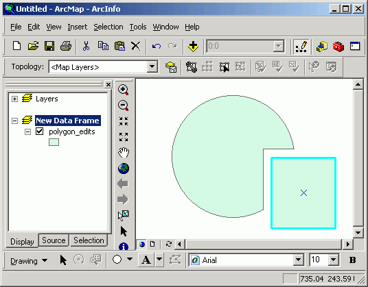
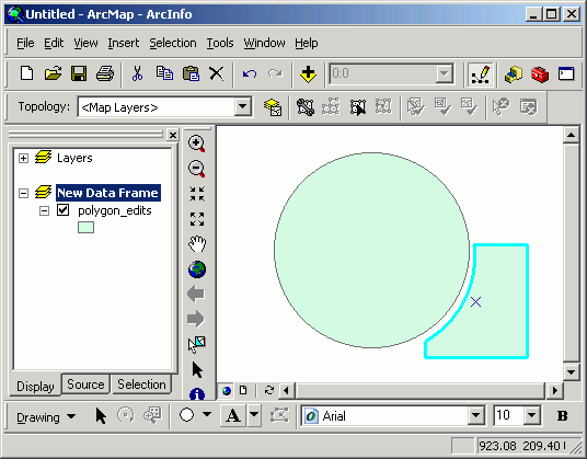
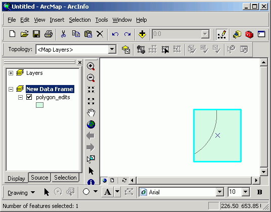
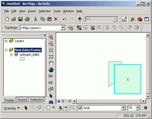
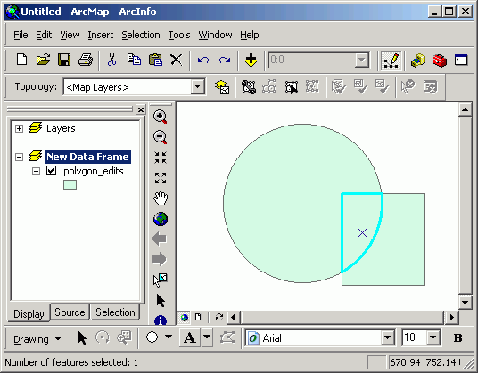
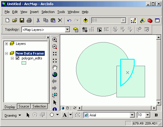
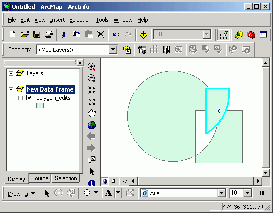
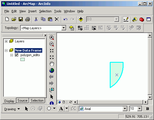
Any edits made to feature classes can be reverted by selecting Edit > Undo from the menu or using the keystroke combination <CTRL-Z>. All edits are able to be undone, up until the last save was performed, or up to the creation of the feature class if the feature class is new and has never been saved.
If you have finished editing a feature class, you can choose to save edits. It is also a good idea to save edits on a frequent basis in case of system problems. Any edits that are saved are written to the disk as part of the feature class's structure.
You will be prompted to save edits if you attempt to stop editing.
You will also be prompted to save changes if you attempt to close the map document, open another project, or close ArcGIS.
Return to top | Ahead to Help Topics
|
|||||||||||||||

|
The University of Washington Spatial Technology, GIS, and Remote Sensing Page is supported by the School of Forest Resources |
School of Forest Resources |