TAPESTRY: The Art of Representation and Abstraction
Common Errors and Mistakes when Pointing
Reference Planes
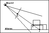
The most common mistake that beginners make when working with 3D programs is forgetting where the construction plane is. The section shown below is cut through one block and we wish to draw another block "on top" of it, as shown in the figure below. We might very well indicate point #1 during the process of drawing the "upper" block thinking that we are indicating a point on the top of the first block. If we have not taken care to set the construction plane correctly, the program will think we mean point #3 and we will produce the second block on the ground, rather than in the desired position on top of the original at point #2. The insidious thing is that both interpretations yield identical axonometric wire-frame views!

|
This is a section-cut of you looking at an axonometric display on the screen. If you Click the mouse at point #1 on the 2D screen, there is ambiguity about where you are pointing in 3D space. Two of the possibilities are illustrated below, assuming ... | |
| ... the program thinks the click is at point #2 (the upper point)... | ..the program thinks the click is at point #3 (the lower point)... | |
| The axonometric view of the results look the same, but ... |
 |
 |
| the Plan views are quite different. |
 |
 |
Snaps and Orthogonal Views
Plan and elevation drawings are ambiguous, as we've seen before. If we are looking at the "Top" view of a cube, and "snap" to one of the corners, we need to remember that there are TWO points which should be equally valid in the snap–one at the top of the cube and one at the bottom. Which one will the program choose?
| You may be able to discover a logical and consistent behaviour with regards to this question, but the "sure fire" method of dealing with it is to select an axonmetric view in which the "target" corner(s) are unambiguously visible. |
Snaps and Not-snaps
Some awkward and unfortunate consequences can occur to users who don't consider the interaction which might occur between features. When searching for an object snap, for example, most programs limit the search area to a small region right around the cursor. If no point is found, the program reverts to a "reference plane" calculation. Thus a "near miss" object snap can end up indicating a very different location in space. For example, the "MOVE" command operates by modifying each coordinate of the moved object by a uniform amount (if I add (0,0,3) to the coordinates of each vertex of an object, it moves 3 units in the Z direction). One straightforward way to get the "deltas" (the amounts to move in the X, Y, and Z directions) is to have the user select two points with the mouse, and then find the deltas by comparing the two points.If the user selects the two points using a single construction plane, the move will always be parallel to the construction plane because both points will have one coordinate in common. If the user select both points using object snaps, they can command an unambiguous "Put that, there!" in 3D. However, if one of the points is selected using an object snap, and the other is selected in the construction plane, the object may move in a very surprising way.
| This is almost never a good idea. |
Snaps and Orthogonal Views
Architects are used to compartmentalizing their representations. They show horizontal locations in the plan views, and vertical positions in the elevations and sections. Thus, while they know the plan represents a 3D space, they may use 2D logic.For example, I once tried to line up two windows on opposite sides of a building using snaps. I selected the window I wanted to move, and then used snaps to show how the two objects should line up. It lined up just fine, as far as the elevation went, but it wasn't right. My snaps had also "pulled" the window across the building, so that the two windows were literally superimposed, not just superimposed in elevation. In the process it really twisted the wall in which it was placed!
| This is a difficult problem to circumvent, unless the program has a feature such as form•Z's "project onto reference plane" option, which projects the two defining endpoints of a move onto the reference plane, and then calculates the deltas. This results in movements parallel to the reference plane, which is consistent with thinking such as mine in the example above. |
Last updated: April, 2014
