Introduction to Geographic Information Systems in Forest Resources
| Introduction to Geographic Information Systems in Forest Resources |
|
|||||||||||||||
|
|||||||||||||||
The topological overlay processes lie at the core of the original ArcInfo toolbox. In fact, topological overlay is what ArcInfo and its predecessors, such as Odyssey, were originally designed to do. Topological overlay allows us to ask questions like "Where are locations that are on unstable soils, and with a slope in the range of 25-40%, and that were harvested within the last 15 years, and on low productivity sites, and what is their percentage of area with respect to the entire watershed?"
Topological overlay is a process whereby separate layers sharing the same spatial extent are merged in different ways. The landscape architect Ian McHarg developed an analog method, a precursor to the digital implementation within GIS . His approach was to take maps traced on sheets of acetate or mylar, and place one on top of the other, and tape the stack to a window or atop a light table. Areas of overlap were darker than areas that did not overlap. The GIS performs in a similar manner, except that the input and output is more accurate and precise, and easier to manage.
The reason these operations are known as "topological" overlay is because the overlay process includes the rebuilding of the topological relationships that make layers function. In the GIS, where lines intersect between one layer and another, vertices are created. Where lines or points share the same space as polygons, the lines and points inherit the attributes of the spatially corresponding polygons. New layers are formed which can take on the attributes or coordinate properties of input datasets. Some or all features from the input datasets are passed on to the output. Attribute values from both input datasets are passed on to the output dataset.
Topological overlay is different from the Select By Layer operations described in the last lesson. In the Select By Layer operations, ArcGIS only looks at the spatial overlap of the features of two layers, and creates a new selected set in one of those layers; no new datasets are produced; no attribute updates are made. In Topological overlay, new layers are created whose geometry and/or attribute structure are altered. Topological overlay allows us to find overlapping features, as well as to quantify the area or length of overlap.
Buffering is a separate topic from topological overlay, but is frequently bundled with overlay because more often than not the results of buffering are used in subsequent overlay analyses to quantify the properties of the landscape within a buffer area.
Topological Overlay
Topological Overlay Types
Feature Geometry ValuesBuffering
Topological Overlay
In ArcGIS, geoprocessing operations, including topological overlay operations, are accessible through ArcToolbox.
ArcToolbox exists as a dockable window within any of the other ArcGIS Desktop applications (ArcMap, ArcCatalog, ArcGlobe, ArcScene). The overlay and proximity methods for feature classes (shapefiles and geodatabases) are arranged within the Analysis Tools tree within ArcToolbox:
A similar set of operations is available for ArcInfo coverage data:
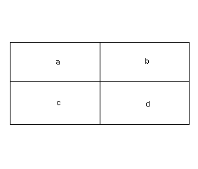
The following cartoon layers will be used to illustrate the functionality of each different topological overlay operation. The sample layers are Ring and Box. Note that the Ring layer has a numeric attribute, while the Box layer has a text attribute. Where the numeric value is undefined, ArcGIS will place a 0; where the string value is undefined, there will be no value at all.
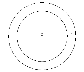
Ring
Box
Each of the overlay operations results in new datasets. For output datasets, feature geometry is almost always modified. In cases where geometry is modified, it is possible to update geometry attributes (e.g., area, perimeter, length). the recalculation of geometry, plus the joining of user attributes, is what gives the power to the overlay operations.
Topological Overlay Types
Appending is used to merge together multiple data sets that represent the same thematic data, but are contiguous. Here is an example that shows two individual shapefiles of Public Land Survey Sections. In the image below, you can see the 2 data sets (sections_north and sections_south; note the full data sets are partially obscured by the forest outline).
After the Append, there is a single data set (sections).
Union
When 2 layers are Unioned, all features from both input layers are combined. All attribute items from the input layer and overlay layer are included in the output. The order of inputs does not matter.
input layer
union layer
output layer

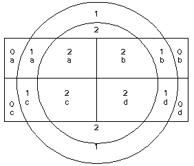
Wherever you see an intersection between lines in the output, there is a node. Each enclosed area you see is a separate polygon with its own record.
Note how the null areas from each of the input layers are either null (for a character item) or 0 (for a numeric item). In the output, outside the box, there are null values for the text field. Outside the ring, there are null values for the numeric field. Also note how all input features have been retained, but new polygons have been created at intersections of input polygons. Attributes are merged where there are areas of overlap. Where there is no overlap, only the input attributes are preserved.
Here is an example of a union of some forest stand and soils polygons.
Soils:
Stands:
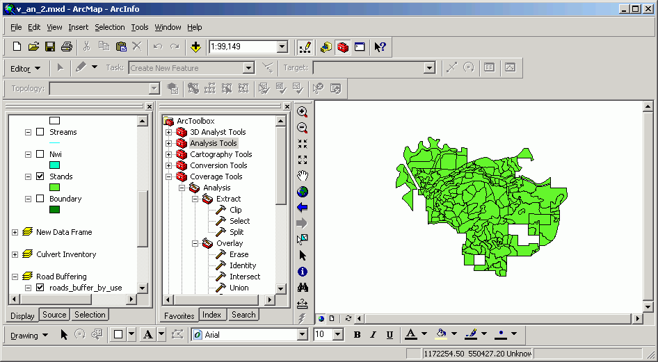
Note how all of the features from both original datasets persist in the output dataset. Wherever there are areas of overlap, new polygons are created.
An identification of one of the polygons shows the output dataset to contain attributes from both input datasets (soils attributes in green, and stand attributes in red).
Identity
The Identity function maintains all features of the input layer, but takes features from the identity layer that overlap with the input layer. The output layer's coordinate properties are dependent on which of the inputs is the identity layer. This is very similar to the Union function, but it includes a clip to the polygon boundary of the input layer.
The spatial exntent of the output of identity operations using the same source data sets will differ if the order of the input and identity layers is switched.
input layer
identity layer
output layer
input layer
identity layer
output layer
Note how in the identity function, order of precedence is important. In places where there is overlap, all attributes have been joined. Where there is no overlap, only input attributes have been retained.
Here is an example of an identity performed on National Wetland Inventory (NWI) as the input layer with stands as the identity layer. The output layer has the same spatial extent as the original NWI layer, but if you look carefully, you will see there are additional polygon boundaries, formed by the overlap of stand polygons on NWI polygons.
The attributes are also joined in an identity, as shown in the results of this identify:
Intersect
The Intersect operation is similar to the other overlay commands, but only areas which are common between the two inputs are included in the output. Unlike in identity, in intersect the order of input layer and intersect layer does not matter.
Input layer
intersect layer
output layer


The only areas that exist in the output are areas that are present in both inputs (similar to an intersection of mathematical sets). For these areas, all attributes from both inputs are preserved.
Here are the same input datasets as before, with an intersect performed on the stands and NWI layers. The output dataset (in pink) is spatially limited to the area in common between the input layers. The light blue in the background is the original NWI data set, but you can see the pink data set is clipped by the edge of the forest stands.
The intersected data also have attributes from both input datasets.
Update
Update replaces overlapping parts of the input layer with features from the update layer.
Input layer update layer output layer
input layer update layer output layer 

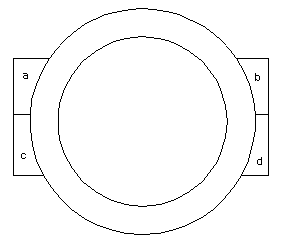
As with Identity, order of precedence is important with Update. Only the attributes in the input layer exist in the output layer. Where there are no values for particular fields, the values will be null (null values are blank for string fields, 0 for numeric fields).
Here, the soils data have been updated by the lakes data. The new layer has new polygons from stands that have been added and overwritten any existing soils polygons. This image shows the original soils data.
And updated with the lakes:
Here one of the new polygons is selected. Actually there are two polygons due to overlapping of the update polygons on the original soils.
Clip
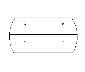
Clip clips out parts of the input layer with the outer shape of the clip layer. Only attributes from the input layer are retained.
Input layer
clip layer
output layer


input layer
clip layer
output layer


Clip's order of precedence also matters, as you can see from two sets of different images above.
Here are is the set of culvert inventory polygons created earlier for the Pack Forest area, clipped by the administrative boundary. Only the original inventory area attributes remain.
You can see that within the administrative area the internal boundaries are the same as the original data set, but the new data set is spatially limited by the administrative boundary.
An intersection of roads and the boundary would have created a dataset with the same spatial properties as this output, but boundary attributes would also have been placed in the output attribute table.
Erase
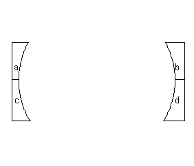
Erase removes parts of the input layer layer based on the spatial properties of the erase layer. Attributes from the input layer are passed to the output layer, and none of the erase layer's attributes are transferred to the output. As with some of the other topological overlay operations, the order of input and erase layer matters.
Input layer
erase layer
output layer


input layer
erase layer
output layer


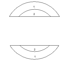
Here is the soils layer erased, using the lakes as the eraser. Any areas in the soils layer that overlap with lakes polygons are erased. The output attribute table has the same structure as the input (soils) attribute table.
One of the main reasons for performing any type of topological overlay is to obtain quantitative measurements of the overlap between layers. Length of line features and area and perimeter of polygon features is an inherent property of the features, but these measurements are not always present in attribute tables, and only in some cases are the geometry measurements updated during overlay processing. Here is a synopsis:
When processes alter coverages or geodatabases, the geometry fields are automatically updated. If processes change or create new shapefiles, the geometry fields are never updated automatically. It is necessary in these cases to update the values manually by using field calculations. This is one more good reason to store your data in geodatabases rather than shapefiles.
Buffering
Buffering creates polygons which are buffered a specified distance from input points, lines, or polygons. Buffers are used to locate and quantify the areas within a specified distance of existing features, such as the area of a riparian management zone, the no-touch zone around a spotted owl nest, or the possible area serviced by a water or sewer network. There are many options for using buffers, including variable-width buffers based on attribute items. For a full treatment, please see the on-line documentation.
Here are variable-width buffers created around roads, where major roads have wider buffers.
And variable-width buffers created around streams, where major streams have wider buffers:
Return to top | Ahead to Help Topics
|
|||||||||||||||

|
The University of Washington Spatial Technology, GIS, and Remote Sensing Page is supported by the School of Forest Resources |
School of Forest Resources |