In order for the HDR image to be displayed in a low dynamic range format, hdrscope performs a conversion to BMP or GIF format through the ra_bmp or ra_gif Radiance commands (Falsecolor images are always displayed using uncompressed BMP format). For larger images, the image display method would determine the speed of conversion from HDR to image display format. For higher accuracy, BMP may be chosen and for faster display performance, GIF format may be chosen.
For every post-processing command that is issued from the GUI, the new HDR image is regenerated (and saved in the cache directory), converted to BMP or GIF and reloaded in the image display area.
hdrscope recognizes RGBE files (.hdr and .pic) as valid file inputs. When RGBE files are opened through the File > Open menu option, the software calculates and buffers the per-pixel luminance values by applying the formula:
L = 179 * (0.2126R + 0.7152G+ 0.0722B)/Exposure
The exposure value is the product of the various exposure corrections performed on the image. The Luminance values are represented with floating point precision and all image processing and analysis is performed in the Luminance domain.
The HDR files can be saved in the RGBE format, JPEG, BMP or GIF formats using File > Save As option. When saving in HDR format, the software creates a copy of the latest cache image in the destination provided. When saving in JPEG format, the tone-map option specified in the Tools > Settings dialog box is used. This method of converting HDR to JPEG format uses default command line switches for the Ward et al. Histogram method or Reinhard et al. Photographic tone-map operators.
[Top]
Camera Capture Automation
Through the Capture menu item, it is possible to remotely connect and control aperture and shutter speed values of certain connected and supported Canon cameras. This option allows users to save captured JPEG image files in a specified folder, set capture modes and time the configured capture to repeat over a period of time. These features eliminate errors during capture process and also ensures that constant observation is unnecessary for capturing images for prolonged periods of time.
In the “Automatic” capture mode, the software selects a predefined set of aperture and shutter values based on a file (which can be modified by the user). This file “autocap.asf” is located in %APPDATA%\hdrscope and is specific for Canon cameras only. Depending on the camera model, the autocap.asf file may need a separate download. The Automatic capture mode is a pessimistic capture mode. The mode always captures images at closer F-stop values and it is the user’s responsibility to either choose the required exposures or allow the HDR assembly software to skip additional exposures. In the “Manual” capture mode, the software allows setting shutter speed values to the camera for a single aperture or two aperture settings. The allowable values are set automatically in the shutter speed selection controls depending on the camera model connected to the PC.
The camera can also be configured to capture multiple exposure image sequences in a loop with a delay set in minutes. The parameters for capture can be modified during the countdown period. The other features in hdrscope can also be used while the capture is counting down.
Note that during the capture process, the user interface is locked down and no user inputs are allowed. Forcing user inputs may alter the state of the software and may result in unintended output.
Installation of camera dependent files such as the camera DLL files is the user’s responsibility. Hdrscope does not bundle these library files in the setup procedure. For details on downloading cameras specific drivers and files such as the SDK, please refer to the Canon website for software specific to the camera.
[Top]
Selection Tools
hdrscope provides three region selection tools that can select pixel regions for a crop operation or perform hit-testing to analyze regions of interest in the lighting analysis process.
The selection tool type can be chosen from Tools > Selection Tool menu option. As explained earlier in the mouse shortcuts section, the method for selecting the region depends on the type of drawing tool selected. Pressing the escape key clears the display region of any drawn shapes. Rectangle selection tool may also be used to select a region in the image to crop. Once a rectangular region is drawn, choosing Edit > Crop will crop the HDR image according to the values defined by the rectangular region. More information about the crop operation is available in the cropping section.
While selecting regions using a rectangle, it is possible to move and resize the rectangular region by following the mouse cursor indications. Double clicking on a valid rectangular region will enable a dialog box with numeric inputs that can precisely control the rectangular region. It is also possible to move (but not resize) circular regions. To provide an easy way of selecting regions that may align with specific points and linear elements in the HDR image, guidelines may be enabled from the Tools > Selection Tool > Guidelines option.
[Top]
Vignetting Correction
This is an optional step during image post-processing that may apply to HDR images that were generated from a fish-eye lens. Lens Vignetting is an artifact that arises owing to lens optical and mechanical deviations. For fish eye lenses, Vignetting introduces a radial non-linear light intensity fall off across the lens. On the periphery of these lenses, the actual light captured by the digital camera image sensor is lower than what is theoretically expected.
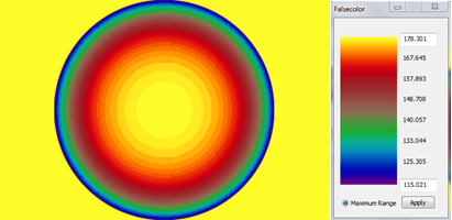
The above image shows the intensity of light as a relative measure of luminance values in falsecolor representation for aperture F5.6. Values in yellow represent pixels that require no luminance modification and other colors require proportional luminance correction. Vignetting correction is performed with the help of a HDR image filter mask that may be specified in the GUI under Edit > Vignetting Correction > Use Maskfile.
These masks may be calculated as explained here. The radiance command for performing vignetting correction for a HDR fish eye image (image_in.hdr) with a known mask (mask.hdr) is:
pcomb -e "ro=ri(1)/ri(2);go=gi(1)/gi(2);bo=bi(1)/bi(2)" image_in.hdr mask.hdr > image_out.hdr
This command is automatically applied by hdrscope when the user chooses the Vignetting correction option and specifies the mask file path. Note that the image pixel resolution of the Vignetting correction mask image must match that of the currently displayed image for Vignetting correction operation.
[Top]
Cropping and Resizing
Large resolution HDR images and certain HDR images involving fish eye optics may require resizing and cropping of unwanted regions. These operations reduce the number of available pixels to what is required for analysis and thereby reducing the processing time for the various Radiance commands for further analysis.
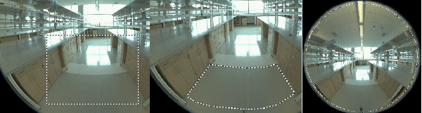
A specific use of the crop feature is to remove unwanted pixels that may arise during fish eye image capture. In such cases, selecting the circular region using the rectangular selection tool and performing a crop operation will yield the intended result.
Once the rectangular crop region is selected, Edit > Crop will perform the crop operation. The Radiance command issued for the crop operation is:
pcompos -x (width) -y (height) image_in.hdr –(xoffset) -(yoffset) > image_out.hdr
where width and height are the corresponding dimensions for the selected rectangle; xoffset is the pixel x co-ordinate offset of the top-right corner of the selection rectangle and yoffset is the minimum of number of rows above or below the selected rectangle. Note that the Crop function works only when the selected region is a valid rectangle and does not work for circular or arbitrary polygonal regions.The image resize function is useful to scale up or scale down the HDR image. Using Edit > Resize option, the image X and Y resolution can be independently altered or changed by retaining the aspect ratio of the original image.
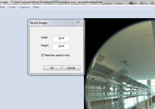
The Radiance command used for this purpose is:
pfilt -1 -e 1.000 -x (xres) –y (yres) image_in.hdr > image_out.hdr
where xres is the desired output X image resolution and yres is the desired output Y image resolution.
Note that in order to retain the current image exposure, an exposure multiplier of 1.000 is applied through the –e option of the pfilt command to the image resize function.
[Top]
Masking an Image
Image masks maybe applied from the Edit menu to an HDR image to exclude pixels that may not participate in the lighting analysis. A common use for image masks is when the additional pixels that belong to the fish eye lens frame need to be excluded since they do not contribute useful pixels to the lighting analysis.
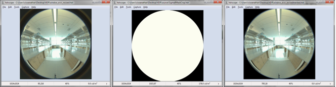
Image mask files maybe of HDR, PIC, BMP or TIFF format. Mask files have to necessarily be of binary nature (black and white) where regions of white are unmodified and regions of black pixels are converted to black pixels. For the purpose of masking, the software treats all RGB pixels below 0.5 (in HDR format) as black or masked pixel and above 0.5 as an unmasked pixel. No adaptive thresholding to convert color to binary is performed. Hence, the corresponding Radiance command for the masking operation is:
pcomb -e "ro=if(ri(1)-0.5,ri(2),0);go=if(gi(1)-0.5,gi(2),0);bo=if(bi(1)-0.5,bi(2),0) mask.extn image_in.hdr > image_out.hdr
where mask.extn is the mask file in the appropriate file format as discussed above. The software automatically converts TIFF and BMP mask files to temporary HDR mask files through ra_tiff –r or ra_bmp –r commands.
Note that the image resolution of the mask file has to match the image resolution of the target HDR image.
[Top]
Rotating and Flipping an Image
HDR images may also be rotated or mirrored about the central X or Y axis of the image through the Edit > Rotate/Flip menu item.
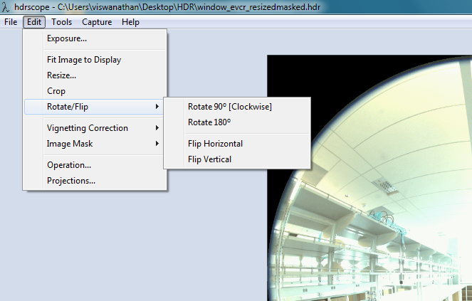
The Radiance commands used for rotation and flipping are as follows:
Rotate 90- protate image_in.hdr > image_out.hdr
Rotate 180 – pflip –c –v –h image_in.hdr > image_out.hdr
Flip Horizontal – pflip –c –h image_in.hdr > image_out.hdr
Flip Vertical – pflip –c –v image_in.hdr > image_out.hdr
[Top]
Image Operations
For scenarios involving comparative studies of different designs (an example – dynamic facades), it may be useful to compare two scenarios through a mathematical operation such as subtraction. Image operations facilitate this method of analysis by calculating an output image that is a combination of two source images. The combination maybe addition, subtraction, multiplication or division of two HDR images to yield an output HDR image. To select an image operation, choose Edit > Operation from the menu bar.
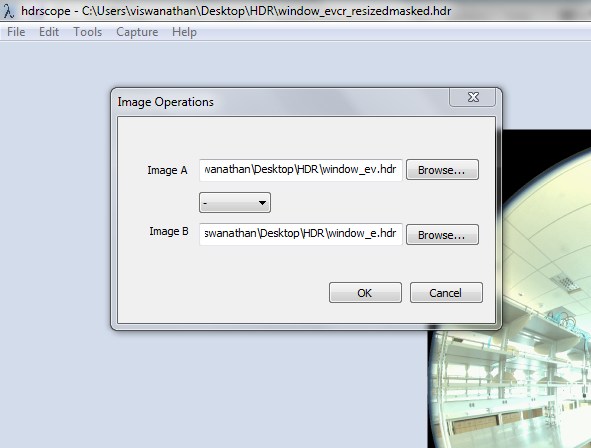
The image operation dialog box allows the user to browse for the source HDR images that participate in the image operations process as well as specify the operation through a drop down list.
The Radiance command for image operations used by hdrscope is:
pcomb -e "ro=ri(1) op ri(2);go=gi(1) op gi(2);bo=bi(1) op bi(2) image_in_a.hdr image_in_b.hdr > image_out.hdr
where op may refer to one of +, -, / or * and image_in_a and image_in_b are the input source images.
[Top]
Exposure Adjustments
Exposure value for a HDR image determines the proportional RGB value for image display. Since exposure is a multiplier applied to the RGB values, it can be modified to alter the displayed image with the necessary intensities. This option can be accessed from Edit > Exposure.
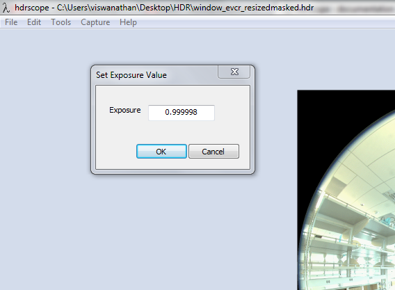
The Radiance command for exposure correction is:
pfilt -1 –e (exposure) image_in.hdr > image_out.hdr
where exposure is the ratio of the desired exposure value to the current image exposure value.
[Top]
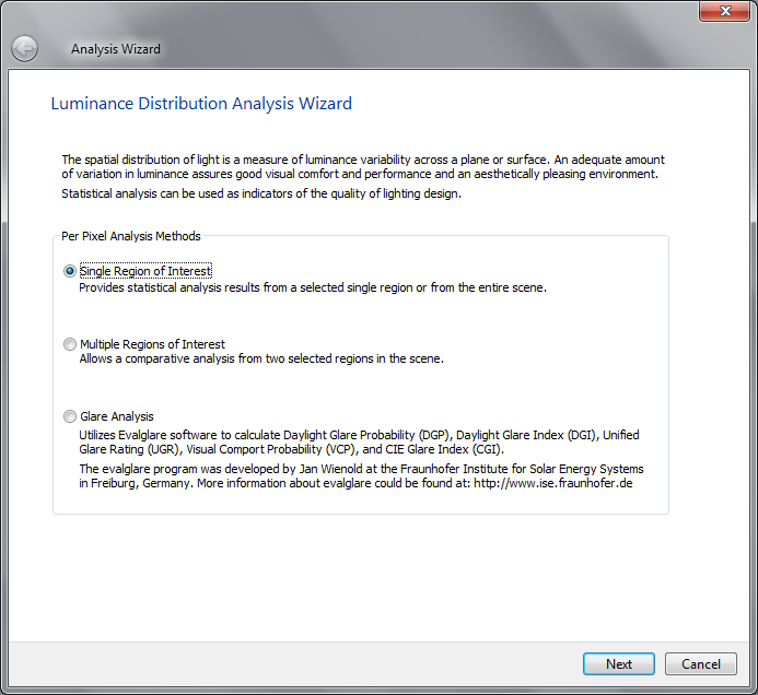
Statistical Analysis
Once the HDR image is processed and prepared for analysis, the Tools > Analysis menu provides the three statistical lighting analysis options in a wizard format.
Statistical analysis provides basic regional statistics such as minimum, maximum, mean, median and standard deviation of luminance values in a selected region or through a mask file. Apart from these values, depending on the type of analysis, it may be possible to retrieve other important statistical data. These are explained in the sections below.
Regional analysis depends on user inputs for selecting a valid region from the image. If the user opts to select a region using the selection tool, the user can return back to the wizard by pressing the ENTER key after choosing a valid region. A mask file may also be specified in place of the selection tool.
Note: All pixels with luminance values 0.0 are ignored during statistics calculation.
[Top]
Single Region of Interest Analysis
This option is useful to retrieve statistics based on a single masked or selected region in the image. Unique to this option, the following analysis features can also be utilized:
- Percentile ratio
- Criterion rating
Percentile ratio calculations are performed by sorting the luminance values and retrieving the upper and lower percentile number of pixels as specified by the user and calculating the ratio of the mean values of luminance within these regions.
Criterion rating performs an absolute comparison of luminance values based on a given condition (lesser than, equal to or greater than a user specified luminance value). The final statistic is represented as the percentage number of pixels in the selected region that satisfies the specified criteria.
The resulting output from the single region analysis wizard is a histogram, basic statistics data and the chosen analysis specific options. Shown below is a sample analysis wizard output:
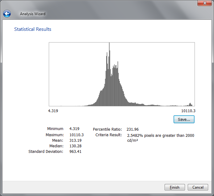
The histogram displayed in the results window is a subset of the Ward histogram method (Radiance phisto script). The only difference is that the histogram calculations do not scale down the image to a 128x128 image. Hence, the histogram calculations in hdrscope may take a longer time to calculate since the entire pixel samples are taken into consideration. The histogram X axis is linear in display. The Y axis is also linear, but normalized by the phisto script and hence the label is not included with histogram graph display.
The results may also be saved in a comma separated values format. The values saved include the statistical data as selected by the user, the histogram output as generated by the modified phisto script and the spatial information of the region selected including its co-ordinates and corresponding luminance value.
[Top]
Multiple Region of Interest Analysis
In order to perform a comparative analysis of the luminance distribution within the scene, this wizard option may be chosen by the user to calculate ratios between two architectural elements or contrast between a task surface and its background.
Multiple regions of analysis allow the user to choose two regions (A and B) independently using selection tools or a mask image. For ratio calculations, Region A is assumed to be the numerator in the mathematical division (or the foreground region for contrast calculations).
Contrast calculations are useful when calculating the luminance of a task and the background, or the foreground and the background.. The contrast is calculated in hdrscope from the foreground and background regions as they are selected by the user or acquired from mask files.
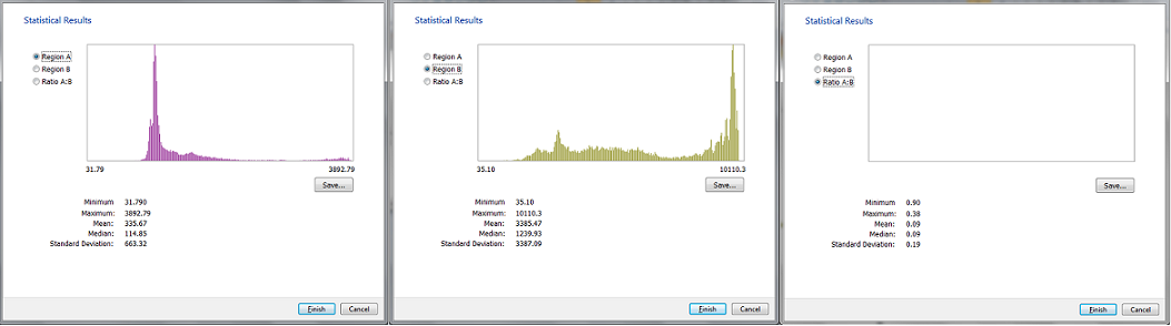
The multiple region of analysis statistics results are presented in three parts. One for each region, and one for the calculated ratios (in which case, the histogram is not shown). The user may choose to individually analyze the regions selected in the wizard or view the ratios calculated for each of the statistics chosen including the ratio of minimum, maximum, median, mean, standard deviation and optionally the contrast. The results may be saved in a CSV file as mentioned previously.
[Top]
Glare Analysis
hdrscope provides a method of analyzing the space for glare through the Evalglare program. Of particular importance in the analysis is the DGP (Daylight Glare Probability) value. Evalglare provides several other features and options for users to customize and specify the characteristics of the glare source. For more information, refer to the Evalglare documentation.
Evalglare program embedded within the analysis wizard exposes all the program features and complies with the suggested work flow. The wizard collects all user inputs required for the glare analysis and runs evalglare.exe at the end of the wizard. Prior to running the evalglare program, the image is scaled down to 800x800 or less to adhere with evalglare program suggestions. Once the wizard finishes execution, the check file created automatically loads in the image display area.
[Top]
Luminance Calibration
In order to ensure that the HDR images maintain absolute accuracy, it may be necessary to calibrate the images through a standard known target and measuring instrument. Luminance calibration may be performed through a standard gray target and by acquiring the luminance value through a spot-luminance meter. By simultaneously measuring the luminance values of the reference target and capturing HDR image sequences, it is possible to linearly calibrate the image. This option is available through Tools > Calibration menu item.
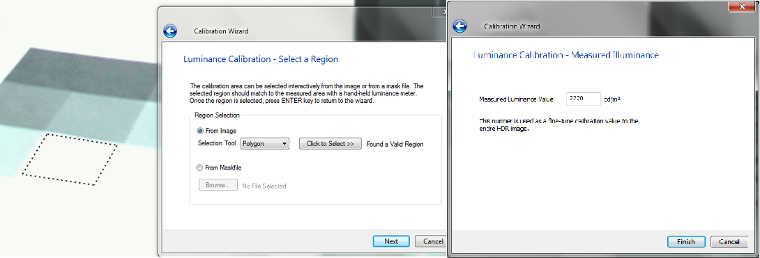
Luminance calibration factor is calculated by selecting the gray target in the scene (through the selection tool or image mask) for which the luminance meter reading is available and then entering the meter reading.
With the reference value, the wizard calculates the calibration factor as a ratio of the average luminance value of the selected region as measured by the digital camera and the measured value as seen in the luminance meter.
[Top]
Iluminance Calibration
For special cases such as sky and sun HDR capture, it may not be possible to perform a luminance calibration owing to the lack of standard test pattern availability for the scenario. In such cases, it may be useful to calculate the calibration factor value from the illuminance measured at the camera level and the illuminance value derived from the luminance values from a fisheye photograph.
Prior to measuring the image illuminance, it is necessary to map the optical behavior of illuminance meters with that of the camera. Illuminance meters are hemispherical sensing systems. The optics in such meters employs cosine correction. Most of the commercially available fish eye lenses however perform a geometrical projection. The image formed on the image sensor is through an equidistant projection of light on the lens. Since this does not reflect the true spatial image information as captured by the illuminance meter, it is necessary to transform equidistant fisheye projections to hemispherical (cosine-corrected) fish eye imagery.
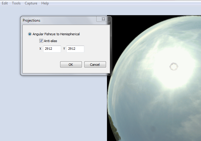
By selecting Edit > Projections, the fish eye image can be transformed to hemispherical projected image and subsequently used to calibrate with illuminance values. Image projections inherently require a cleanup of the HDR image file header and this is automatically performed by hdrscope prior to applying the Radiance command. The following Radiance command is used to transform the picture from angular fish eye to hemispherical fish eye:
pinterp -vf image_in.hdr -vth –x (aliasx) –y (aliasy) -ff image_in.hdr 1 > image_out.hdr
where aliasx and aliasy are anti-aliasing values for image resolution. Alias values are optional and can be specified in the projections dialog box.
Similar to luminance calibration, illuminance calibration wizard requires the illuminance meter value and correspondingly calculates the calibration factor and applies it to the image. The calibration factor is applied to the image through the following Radiance command:
pcomb -e "ro=ri(1)/(calfactor);go=gi(1)/(calfactor);bo=bi(1)/(calfactor)” image_in.hdr > image_out.hdr
The calfactor is calculated by the wizard as the ratio of average luminance value of the selected region to the measured luminance meter value for luminance calibration. For illuminance calibration, illuminance from the image is calculated as the average image luminance calculated from the circular portion of the fisheye image multiplied by π. The calibration factor is calculated as the ratio of the calculated illuminance value to the measured illuminance quantity.
[Top]
Falsecolor
The falsecolor program within hdrscope is a log mapping of the luminance values in the image and can be accessed from Tools > Falsecolor
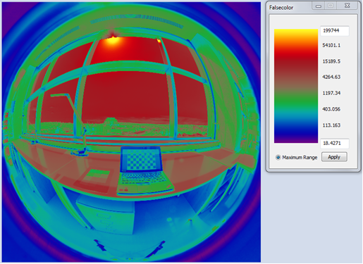
The falsecolor image scale can be adjusted according to the user’s requirements and analysis goals.
[Top]
Tonemapping
Two tone-mapping operators are provided within hdrscope – Reinhard photographic tone mapping operator and Ward histogram tone-mapping operator. These operators are available from Tools > Tonemapping.
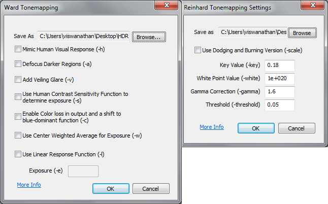
Reinhard’s photographic tone-mapping method provides the user with options to set the HDR to tone-mapped JPG conversion parameters in the user interface. Ward’s method of tone-mapping applies the pcond Radiance command to condition the picture according to the requirements. The dialog box exposes most of the pcond command line options. Since pcond translates HDR images to a conditioned HDR and the purpose of tone-mapping is to generate a “displayable” picture, the tm_linear program is used (without any options set) to translate the HDR to JPG.
[Top]