TAPESTRY: The Art of Representation and Abstraction
EMP Gazebo
Architecture 481: 3d Modeling and Rendering
NURBS: Building an EMP-Inspired Gazebo
The Goal
Imagine that you wish to build a glazed garden gazebo inspired by the Experience Music Project. It will be made of straight steel pipe sections, which will frame flat glass panels, but you want to play with the form a little.
The Challenge
Using NURBS, how do we model the gazebo? NURBS are continuously curved, glass is flat and pipes are straight. Yes, we can get pipes bent, and glass slumped, but that's expensive.
The Process
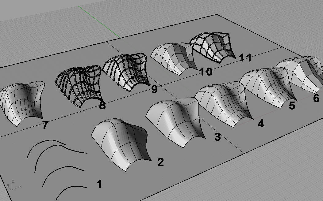
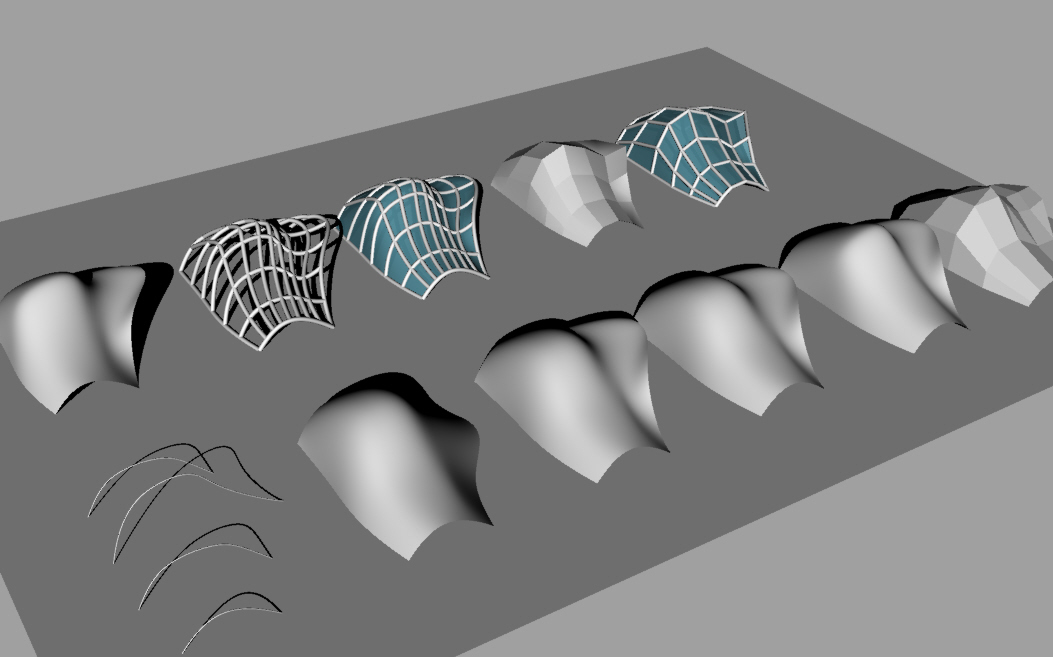
The following steps describe the progression of models shown above, working from left to right across the front (near) row of shapes, then left-to-right across the back row.
- DRAW CURVES
The curves shown here have been piped to make them render, but these are simple spline curves, drawn in FRONT view and then moved to space them approximately equally in plan. - LOFT
The LOFT command prompts you to select the curves. Pick them in order from one end of the shape to the other. - lift the right edge [optional]
After turning "CONTROL POINTS ON" pick the set of points on the "leading edge" on the right side. MOVE these points straight up to raise the "hemline" on the right side. - Object Properites: isocurve density = 2 [optional]
This simply displays more curves no the surface, without changing it. - WEIGHT [optional]
Selecting the three points at the "high point" of the control polygon, control-point weights were increased to 'pull' to top up a bit. This has the side-effect of pulling the adjacent isocurves towards the ridge-line (note how they bunch up a bit). - MESH, from NURBS Object [dead end]
The last form in the front row is a MESH. The "complexity" slider in this command is identical to that used in the ExtractRenderMesh command (as is the mesh). with the associated problem that it can and often does introduce triangular elements into the mesh. However, it gives flat polygons. This line of development is abandoned at this point. - COPY the 4th Surface
The first surface in the back row is a copy of the 4th (weighted) surface from the front row. - ExtractWireFrame + PIPE
ExtractWireFrame creates a spatial curve at each isocurve location. These can then (one at a time) be used with PIPE to make the model shown. Note that the pipes are curved. - Glass + Structure [Possible Solution]
The third form shows a NURBS (curve) surface and Piped NURBS lines, with the surface given some transparency. This is what we were after, but for the fact that it's all curved. Still, maybe this looks good, so we might stop here. - REBUILD to Degree 1
To make the surface flat, the REBUILD command is applied. U & V control points are held to the same values, but the degree of the surface is reduced from 3 to 1, yielding the tessellated shape shown. This procedure produces quadrilaterals (will they always be flat?), unlike the MESH from NURBS used at the end of the first row. - ExtractWireFrame + Pipe + Glass [Final Solution]
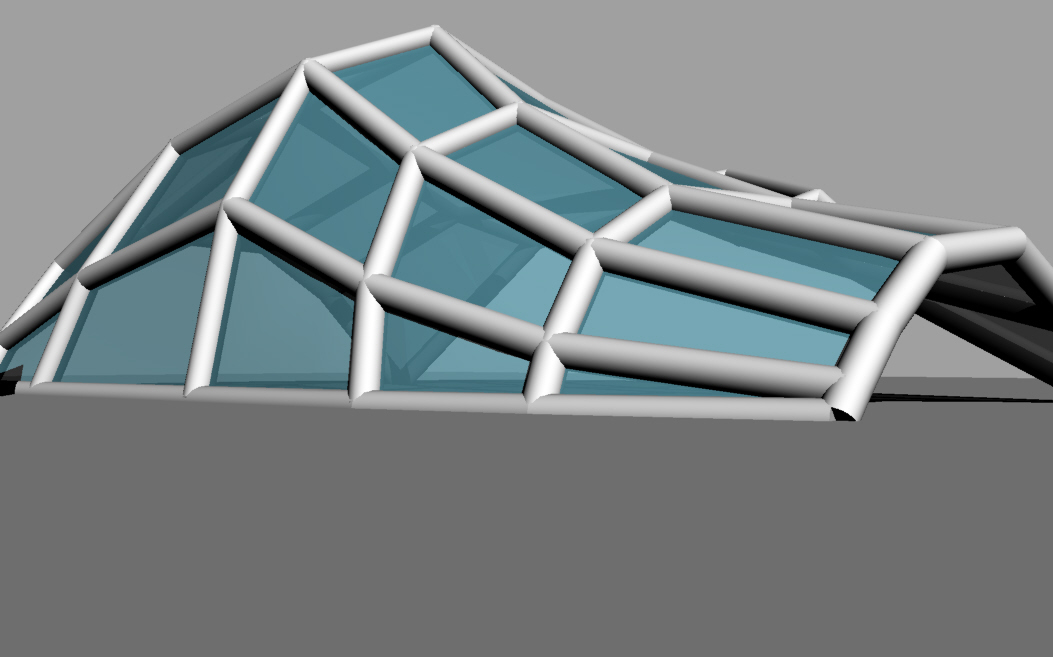
The final variation uses the wireframe+pipe steps applied previously, along with a copy of the degree-1 surface.
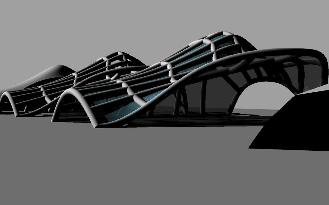
The "Gazebo Field" collection, rendered with Rhino-render
Last updated: April, 2014
