TAPESTRY: The Art of Representation and Abstraction
Hidden Lines and Surfaces
What's it all about?
Rather than "fixing" the problems associated with Depth Sorting (i.e., going through the effort of finding intersecting polygons, which isn't an easy task in boundary representation software anyway), and recognizing that the image will most likely only be displayed on a raster CRT screen, another approach is also possible.
Keep in mind that a standard part of the graphics pipeline is the transformation of model coordinates to an eye coordinate system. When this is done the view vector becomes the Z-AXIS, the the X-AXIS to the right and the Y-AXIS up to the top of the image. For parallel projections this makes it easy to figure out the image coordinates--they're just the eye-space coordinates, but ignoring Z.

But that eye-space Z-coordinate tells us something about where the associated model vertex is in space. With a little thought, we can make use of that, so let's keep it! That means (as shown at right) that each vertex in the model (Model-space x,y,z), produces an image- or screen-space coordinate (u,v,d), where "u" is along the screen's horizontal axis, "v" is the vertical, and "d" is the "depth" or "distance" from the eye to the point in 3D. This is alternatively denoted at right as "(screen.x, screen.y, and eye.depth)".
Rather than pre-sorting polygons as is done in a Depth Sort, we just process each polygon as it comes out of the database. It's coordinates are transformed into the eye-coordinate system, at which point the eye-space Z-coordinates represent "distance into the scene". The 3D points are then projected onto the 2D picture plane.
The resulting screen polygon must then be "rasterized" by filling in the appropriate screen pixels. Because the edges of the polygon are straight in the model, they must be straight in the image too.
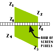
The graphic at left illustrates the situation for a single polygon. The polygon represents the projected image of the 3D data polygon. The white, subdivided band across the middle represents one (of many) rows of pixels (called a scan line) that the polygon partly overlaps. Since the 3D polygon is planar, we can calculate the Z-coordinate of any point along its edge by linearly interpolating between the Z-coordinates of the end-points. Thus, we can calculate the Z-coordinate of the two points (A and B) where the polygon crosses the scan line. Further, we can calculate the Z-coordinate of any point ALONG the scan line by the same process.
Let's say the polygon is uniformly colored green. One part of our algorithm must decide which pixels in the image are going to be made green. This is partly a question of which pixels are overlapped by the projected image of the polygon. However, what if we keep a second "image" containing one pixel for each screen pixel, only in this image we store the eye-space Z-coordinate (the depth) rather then the color! That's what a Z-buffer is, memory in which the z-coordinate of every point on the screen is recorded--almost like a radar picture of the scene, recording the depth of each pixel.
The 'closer than' test
When we start to render the image the "blank" z-buffer contains a depth of "infinity" (i.e. the background) for each pixel. Then we color-in each polygon, one at a time.
When the "coloring in" algorithm rasterizing a new polygon is ready to color a pixel, it compares the Z-value of the proposed ("wannabe") z-buffer value against the current z-buffer value for that pixel. If the new color for the pixel derives from a polygon which is 'closer than' the data we've processed before, the algorithm will color in the pixel and update the Z-buffer with the new (smaller) Z-value. If the 'pixel' is further away, the data is discarded without coloring in anything.
Think about it a bit and you'll see that this solves the problem of the interlocking polygons which was mentioned previously. It does this by changing the question from "Which polygon is closest to us?", to "Which pixel is closest to us?" (That's a little funky, since the pixels are in the screen image and don't move, but it's easier to say than "Which surface is closest to us at this pixel, which is what is really going on, and it conveys the change in focus from polygons to pixels, which is important.)
Note, too, that the order in which the polygons are processed doesn't matter. If we 'just happened' to find the 'front' ones first, the z-buffer would have small (near) Z-values and the rest of the polygons would flunk the 'closer than' test. If we happened to find the front ones last, their z-values would be smaller than the rest of the image and they'd be rendered over the top of whatever came before! Slick!
Raster forever!
Also worth noting -- We've now irrevocably crossed the line into RASTER IMAGES. The fundamental operation of this algorithm relies on only storing and testing a finite number of pixels. Where Culling and Sorting algorithms produced an object-based graphic, Z-Buffer algorithms produce raster graphics.
While we don't have to do any sorting, we *may* do culling. We also pay some additional overhead in the form of memory to store the Z-buffer and processing to "rasterize" the Z-values, but the low-level routines for this kind of work are well understood and we had to rasterize the polygon anyway.
Last updated: April, 2014
