TAPESTRY: The Art of Representation and Abstraction
Model Development
In contrast to a model created after the design is complete, a design model is developed in greater and greater detail as the design project progresses. To do this you need to develop your editing skills to a higher level, because you will be changing, repurposing, or fixing data rather than simply entering data to match some pre-existing notion of the geometry.
The example shown here starts by creating a massing model as a simple formal composition using solid elements. That model then needs to be developed into a schematic design model, complete with windows, doors and so on. If you want to download a form•Z model to experiment with, click on one of the images along the left side of the page.
| Prerequisites | This project assumes the following skills:
|
| Step 1: The Massing Model | |
 |
Your model may well be more complicated, but this building will illustrate the process.
Commands:Use Extrude Rectangle to create cubic volumeUse Converge Rectangle to create three pyramid which later will be used as base to make skylight openings *Make sure Converge Rectangles are sitting 1'-0'' into the cube in elevation. This will prepare you for the next step of Difference command. 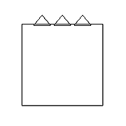 |
| Step 2: The Hollow Model | |
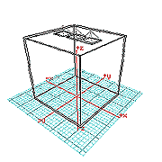 |
The massing model has no real interior and lacks much of the necessary detail. In the next steps you'll hollow it out and begin adding that detail.
Commands:The Parellel Object tool can be used to carve out the inside of even fairly complex shapes, leaving them with a desired wall thickness (we've used 1'-0" here).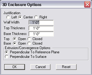 Use the Difference operation (a Boolean operation) to make the skylight openings. Select the wall object as the "first object" and the pyramidal shape as "object to difference from" the first object. You'll have to do this once for each skylight. |
| Step 3: Skylights | |
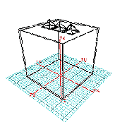 |
Sometimes you will use solid objects in the massing model to represent glazed elements, such as window walls and skylights. The corners, or edges of the "solid" represent the framing elements we need.
Commands:Before we can proceed further, we need to "ressurect" the skylight forms used in the Boolean operations above.Unghost the three pyramids. They will be used as a guides for Sweep command
We will use Sweep to build the skylight framing elements. Sweep needs two rectangles, one representing the cross-section of the frame, and the other representing the overall perimeter of the framed area (the path along which the cross-section is swept). The exact location and orientation of the cross-section drawing isn't important, so simply create a 2D shape near (somewhere easy to see/pick) and keep topological level set to face
This would also be a good time to select a different color, and possibly a different layer.
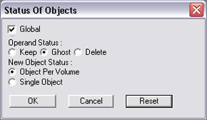
Select 2D shape of frame and select one side of face at a time. You may have to unghost the pyramid several times since it will turn into a ghost after each sweep command by default. Alternatively, you can select the Status of Objects ... button and select NOT to ghost operands. This will generate the new geometry from the pyramid, but leave the original geometry intact (so don't forget to delete it when you get done!).
|
| Step 4: Cut out the Windows | |
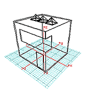 |
The hollowed-out building form will also need window and door openings cut into it. This step illustrates two different ways to do this.
Commands:Insert Rectangle Hole was used with a negative height value greater than the wall thickness to create window openingInsert Rectangle Opening was used to create open door way. Since "holes" alwasys penetrate the object completely in form•Z it is not necessary to enter a "height" for the hole. |
| Step 5: Frame the Windows | |
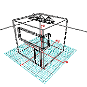 |
In this step you add the door and window-frame trim to the openings cut in the previous step. The Sweep operation will prove useful here too.
Commands:Zoom in and draw a closed vector line representing the cross-section of the trim. By triple clicking at the end you can be sure it is closed. (Note: "the end" is the last explicitly defined point--triple clicking will force generation of the segment connecting this with the first point without creating an extra point). This will become the path for the next step. The small red rectangles in the following images show our cross-sections.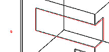 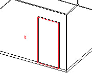 Again, use the Sweep command, selecting frame contour and vector line as the path. |
| Rendering of Finished Model | |
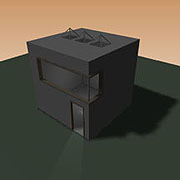
| |
Updated graphics by Nanchhing Tai (Autumn, 2005)
Last updated: April, 2014

